IMPORTANT SAFETY INSTRUCTIONS SAVE THESE INSTRUCTIONS PLEASE READ THE ENTIRE CONTENTS OF THIS MANUAL PRIOR TO INSTALLATION AND OPERATION. BY PROCEEDING WITH LIFT INSTALLATION EUROPEAN USERS AND OPERATION YOU AGREE THAT YOU FULLY UNDERSTAND AND COMPREHEND THE FULL CONTENTS OF THIS MANUAL. 400V 50Hz SUPPLY DETAILS ARE FORWARD THIS MANUAL TO ALL OPERATORS. FAILURE TO OPERINCLUDED WITH ELECTRICAL CONTROL BOX. DISREGARD SUPPLY WIR- ATE THIS EQUIPMENT AS DIRECTED MAY CAUSE INJURY OR DEATH.
14,000 POUND CAPACITY, COMMERCIAL GRADE FOUR POST ALIGNMENT AUTO / TRUCK LIFT This instruction manual has been prepared especially for you. Your new lift is the product of over 40 years of continuous research, testing and development; it is the most technically advanced lift on the market today. READ THIS ENTIRE MANUAL BEFORE INSTALLATION & OPERATION BEGINS.
OWNER’S RESPONSIBILITY IMPORTANT NOTICE To maintain the lift and user safety, the responsibility of the owner is to read and follow these instructions: Do not attempt to install this lift if you have never been trained on basic automotive lift installation procedures. Never attempt to lift components without proper lifting tools such as forklift or cranes. Stay clear of any moving parts that can fall and cause injury.
TABLE OF CONTENTS Contents Page No. Warranty / Serial Number Information . . . . . . . . . . . . . . . . . . . . . . . . . . . . . . . . . . . . . . . . . . .2 Definitions of Hazard Levels . . . . . . . . . . . . . . . . . . . . . . . . . . . . . . . . . . . . . . . . . . . . . . 3 Owner’s Responsibility . . . . . . . . . . . . . . . . . . . . . . . . . . . . . . . . . . . . . . . . . . . . . . .3 Before You Begin . . . . . . . . . . . . . . . . . . . . . . . . . . . . . . . . . . . . . . . . . . . . . .
INSTALLER / OPERATOR PLEASE READ AND FULLY UNDERSTAND. BY PROCEEDING YOU AGREE TO THE FOLLOWING. Failure to follow danger, warning, and caution instructions may lead to serious personal injury or death to operator or bystander or damage to property. t I have visually inspected the site where the lift is to be installed and verified the concrete to be in good condition and free of cracks or other defects.
INTRODUCTION 1. Carefully remove the crating and packing materials. CAUTION! Be careful when cutting steel banding material as items may become loose and fall causing personal harm or injury. 2. Check the voltage, phase and proper amperage requirements for the motor shown on the motor plate. Wiring should be performed by a certified electrician only.
TOOLS REQUIRED t t t t t t t t t t t t t t Rotary Hammer Drill or Similar 3/4” Masonry Bit Hammer 4 Foot Level Open-End Wrench Set: SAE/Metric Socket And Ratchet Set: SAE/Metric Hex-Key / Allen Wrench Set Large Crescent Wrench Large Pipe Wrench Crow Bar Chalk Line Medium Flat Screwdriver Tape Measure: 25 Foot Minimum Needle Nose Pliers NOTE: An air supply (30 PSI Min / 3 CFM Min.) will be required for the safety-lock mechanisms. See Step 11.
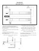
DANGER! When removing the lift from the shipping angles, pay close attention as the posts can slide and can cause injury. Prior to removing the bolts, make sure the post are held securely by a fork lift or some other heavy lifting device. IMPORTANT NOTE ! The Power Unit must be installed at the location shown above. It is important to locate the POWER SIDE RUNWAY (with Cylinder) on the SAME SIDE as the Power Unit Location.
FLOOR PLAN *IMPORTANT NOTE* Check Diagonal Measurements To Ensure Square Layout Diagonal Measurements Must Be Equal. MODEL Lifting Capacity HDS-14LSX HDS-14LSXE 14,000 Lbs /6,350 Kg. 14,000 Lbs. / 6,350 Kg. Max Capacity Front Axle 7,000 Lbs / 3,175 Kg. 7,000 Lbs / 3,175 Kg. Max Capacity Rear Axle 7,000 Lbs / 3,175 Kg. 7,000 Lbs / 3,175 Kg.
CLEARANCES HDS LIGHT DUTY APPROACH B. Place target on floor at column positions (NOT on column base plates) and record readings. 1. Lift Location: Use architects plan and Engineers automatic level (transit) when available to locate lift. The above shows clearances of a typical bay layout. Lift floor area should be level. C. Find the highest of the four locations. Find the difference between the readings at each of the remaining three columns and the highest reading. 2.
The Power Unit will be located at the location shown below. It is important to locate the POWERSIDE RUNWAY ( with Cylinder) on the SAME SIDE as the POWER UNIT. Note the location of the Flex hose holes in the POWERSIDE RUNWAY. Rolling Jack / Utility Rails on the side of each runway MUST be installed to the inside.
STEP 3 (Column & Cross Tube Installation) 1. Place a chalk line on the floor according to the floor plan layout. Pay attention to the Power Unit location. Locate and stand the Columns at their respective locations. DO NOT BOLT Columns down at this time. Use caution to prevent the Columns from falling over. (See Fig. 3.1) Fig 3.3 Fig 3.1 2. To estimate the shim requirements, place a target on floor at each Column position and record the readings.
2. Manually raise the Cross Tubes until the Primary Safety Locks engage and rest on the third or fourth lock position or approximately 24” off the ground. It is important that the SLACK SAFETY LOCK IS CLEARED. The Slack Safety Lock must never rest on the Safety Ladder. (See Fig. 4.1 - 4.3) 5. The Columns and Cross Tubes will now be in position and spaced properly for the Runways. 6. Thread the jam nut all the way to the Ladder. Install the column TOP CAPS using the M16 x 2 Hex Bolts, nuts & washers.
4. Position the Powerside Runway on top of the Cross Tubes with the utility rail towards the center. The fitting holes located at the side of the Powerside Runway should be adjacent to the Power Unit Column. Align the holes in the runway with the holes on the Cross Tubes and bolt together using four M12 x 1.75 x 90 hex bolts and washers. Tighten to 80 Ft/lbs. (See Fig. 5.5) STEP 5 (Powerside Runway Installation) 1.
STEP 7 Fig. 7.3 (Sheave Installation) DANGER! DO NOT PROCEED unless visual confirmation is made of ALL Safety Locks. ALL Locks MUST be engaged before proceeding. Failure to comply with these instructions may result in severe personal injury or death. (See page 11.) 1. Inspect cables to insure proper lengths. All CABLES should have ID tags showing proper Cable lengths. Fig. 7.4 2. Review the Cable Routing Diagram below before beginning cable installation. (See Fig. 8.1) 3.
STEP 8 (Cable Installation) WARNING ! WHEN THE CABLE ADJUSTING NUTS BOTTOM OUT ON THE THREADED END OF THE CABLE CONNECTOR AND THERE IS STILL SLACK IN THE CABLES, THE CABLES HAVE STRETCHED BEYOND THE SAFE USEFUL LENGTH AND NEED TO BE REPLACED WITH FACTORY APPROVED CABLE ASSEMBLIES. DO NOT PLACE WASHERS, SPACERS OR OTHER DEVICES TO “SHORTEN” THE EFFECTIVE CABLE LENGTH AS DAMAGE TO THE LIFT OR INJURY TO PERSONS MAY OCCUR. Cable Routing Diagram A B Fig 8.
1. The Cylinder Flange plate MUST be installed with the guide assembly facing down, welded on Spacer towards the Cylinder and the Cylinder Retainer Plate on the outside of the guide. Lug ends of Cables start at Cylinder. (See Fig. 8.3) DANGER! Failure to route lifting Cables as described may lead to serious personal injury and/or death to operator or bystander and/or may cause damage to property. Fig 8.3 HELPFUL TIP Pay careful attention to the labels on the cabels.
4. Secure using the M22 Hex Nuts and Flat Washers. Tighten each nut until there is at least one inch of thread protruding through the top of the Nut. The Cables will remain loose until start up and final Cable adjustments are made. (See Fig.8.6) STEP 9 (Power Unit Installation) 1. Mount the Power Unit to the Mounting Bracket using the M8 Hex Head Bolts and nylon nuts then fill the reservoir with 12 quarts of 10-WT hydraulic oil or Dexron automatic transmission fluid. (See Fig. 9.1) Fig 8.6 5.
The standard Power Unit for your lift is 220 volt, 60HZ, single phase. All wiring must be performed by a certified electrician only. SEE WIRING INSTRUCTIONS AFFIXED TO MOTOR FOR PROPER WIRING INSTRUCTIONS. WARNING ! DO NOT run Power Unit with no oil. Damage to pump can occur. The Power Unit must be kept dry. Damage to Power Unit caused by water or other liquids such as detergents, acid etc., is not covered under warranty. Operate lift only between temperatures of 41 °- 104° F.
Fig 10.5 90° Air Line Compression Fitting 90° Air Line Compression Fitting 90° O-Ring Fitting 5. Route both the Power Unit Hydraulic Hose and TWO (2) lengths of Air Line through the Flex Hose. (See Fig. 10.6) Fig. 10.2 Fig 10.6 2. Remove the captive nut on the Compression Fitting. Insert the Plastic Air line through the alignment sleeve and into the end of the fitting until it bottoms out. Then tighten the nut on the fitting. (See Fig 10.3) Air Line Hose Flex Hose Power Hose 90° Hose End Fig. 10.
7. Connect the hydraulic hose and air line as shown below making sure the hydraulic hose passes through the retaining rings. MAKE SURE HOSES ARE KEPT CLEAR OF CABLES. There will be one air line hose left unconnected in this step. This air line will be used to activate the pneumatic safety locks in the next step. See page 19 for Compression Fitting instructions. (See Fig. 10.8) Straight Hose End STEP 11 ( Routing Air Lines) 1. Mount the Push Button Air Valve Assembly on to the power unit mounting bracket.
SAFETY AIR LINE ROUTING NOTE: CUT THE PROVIDED 1/4” AIR LINE TUBING WITH A SHARP BLADE TO LENGTHS AS REQUIRED. TUBING MUST BE CUT SQUARE WITH ALL PLASTIC BURRS REMOVED. AIR TUBING ASSEMBLY: SEE PAGE 19 FOR ASSEMBLY OF AIR LINE TUBING INTO FITTING. CAUTION: REMOVING THE AIR TUBING FROM THE COMPRESSION FITTINGS WILL CAUSE DAMAGE TO THE TUBING ITSELF. USE OF A DAMAGED AIR LINE MAY RESULT IN SAFETY LOCK FAILURE.
DANGER! DO NOT PERFORM ANY MAINTENANCE OR INSTALLATION OF ANY COMPONENTS WITH OUT FIRST ENSURING THAT ELECTRICAL POWER HAS BEEN DISCONNECTED AT THE SOURCE OR PANEL AND CANNOT BE RE-ENERGIZED UNTIL ALL MAINTENANCE AND/OR INSTALLATION PROCEDURES ARE COMPLETED. IMPORTANT POWER-UNIT INSTALLATION NOTES n DO NOT run power unit with no oil. Damage to pump can occur. n The power unit must be kept dry. Damage to power unit caused by water or other liquids such as detergents, acid etc.
STEP 12 STEP 13 (Power Unit Hook Up) (Inspecting The Slack Safety Springs) 1. Have a certified electrician run the power supply to the motor. Refer to the data plate found on the motor for proper power supply and wire size. The following steps involve the SLACK CABLE SAFETY DEVICE and MAIN SAFETY. Failure to follow these steps could result in serious injury or death in the event of cable failure. RISK OF EXPLOSION! 1. Inspect the ends of the ALL SAFETY LOCK SPRINGS as shown.
5. Check to make sure that all Slack Safety Locks are cleared and free. (See Fig. 14.1) KEEP HANDS AND FEET CLEAR. Remove hands and feet from any moving parts. Keep feet clear of lift when lowering. Avoid pinch points. 9. Check all MAIN SAFETY LOCKS to make sure they move freely and spring back to the lock position when released. Lubricate all SAFETY PIVOT points with WD-40 or equal. 10.
STEP 16 Fig. 15.2 (Installing Accessories) 1. Install the Approach Ramps on the entry side of the lift. Use the Lower Pin Tube. (See Fig. 16.1 ) 3. After drilling, remove dust thoroughly from each hole using compressed air and/or bristle brush. Make certain that the Columns remain aligned with the chalk line. 4. Assemble the Washers and Nuts on the Anchors then tap each hole with a hammer until the Washer rests against base plate. Be sure that if shimming is required, enough threads are left exposed.
Alignment Turnplate Rollback Spacer 8. Adjust the adjustment nut on the safety ladder bar at the top of the Column at “B” until the cross hairs of the Level align to reference mark on the target scale. (See Fig. 17.1) Ramp Riser 9. Repeat steps locating the target assembly at points “C” and “D” and adjusting Safety ladders at each corresponding column until the reference mark on the target scale is on the cross hairs of the Level. The runways are now level at all four points. (See Fig. 17.1) 10.
POST-INSTALLATION CHECK-OFF STEP 18 (Bleeding) n n n n n n n n n n n n n Columns properly shimmed and stable Anchor Bolts tightened Pivot / Sheave Pins properly attached Electric power supply confirmed Cables adjusted properly Safety Locks functioning properly Check for hydraulic leaks Oil level L ubrication of critical components Check for overhead obstructions All Screws, Bolts, and Pins securely fastened Surrounding area clean Operation, Maintenance and Safety Manuals on
OPTIONAL EQUIPMENT INSTALLATION Rolling Jack maximum weight capacity for use with HDS-14LSX or HDS-14LSXE is 7,000 lb (3,175 kg) per unit. HDS/HDSO-14LSX Rolling Jack Air Line Kit Installation Part # 5174009 REV 03/21/2012 5174009 PART # HD-9/12/14, HDS/HDSO-14LSX/LSXE AIR LINE KIT Description Qty.
Adapter Plate Required for HD-9,12,14, HDS-14 Adapter Plate Required for HD-9,12,14, HDS-14 31
STEP 19 (Operation Instructions) OWNER/EMPLOYER RESPONSIBILITIES The Owner/Employer: • Shall ensure that lift operators are qualified and that they are trained in the safe use and operation of the lift using the manufacturer’s operating instructions; ALI/ SM01-1, ALI Lifting it Right safety manual; ALI/ST-90 ALI Safety Tips card; ANSI/ALI ALOIM-2000, American National Standard for Automotive Lifts-Safety Requirements for Operation, Inspection and Maintenance; ALI/ WL Series, ALI Uniform Warning Label Deca
LIFT OPERATION SAFETY (CONT’D) • ALWAYS keep area around lift free of tools, debris, grease and oil. • NEVER overload lift. Capacity of lift is shown on nameplate affixed to the lift. DANGER! VISUALLY CONFIRM THAT ALL PRIMARY SAFETY LOCKS ARE ENGAGED BEFORE ENTERING WORK AREA. SUSPENSION COMPONENTS USED ON THIS LIFT ARE INTENDED TO RAISE AND LOWER LIFT ONLY AND ARE NOT MEANT TO BE LOAD HOLDING DEVICES.
LIFT OPERATION SAFETY (CONT’D) 2. Raise the lift off of the Safety Locks by pressing the push button on the Power Unit. Make sure you raise the lift by at least two inches to allow adequate clearance for the locks to clear. • Always call local service representative if electrical problems develop. • Always replace ALL FAULTY PARTS before lift is put back into operation. • Every 3 Months: Check anchor bolt torque. Anchors should be torqued to 90 ft/lbs.
WIRE ROPE INSPECTION AND MAINTENANCE t Lifting cables should be replaced every three - five years or when visible signs of damage are apparent. DO NOT USE LIFT WITH DEFECTIVE / WORN CABLES. t Lifting cables should be maintained in a well-lubricated condition at all times. Wire rope is only fully protected when each wire strand is lubricated both internal and external. Excessive wear will shorten the life of the wire rope.
Safe Lift Operation Automotive and truck lifts are critical to the operation and profitability of your business. The safe use of this and other lifts in your shop is critical in preventing employee injuries and damage to customer’s vehicles. By operating lifts safely you can insure that your shop is profitable, productive and safe. Safe operation of automotive lifts requires that only trained employees should be allowed to use the lift.
t DO NOT leave the controls while the lift is still in motion. t DO NOT stand directly in front of the vehicle or in the bay when vehicle is being loaded or driven into position. t DO NOT Go near vehicle or attempt to work on the vehicle when being raised or lowered. t REMAIN CLEAR of lift when raising or lowering vehicle. t DO NOT rock the vehicle while on the lift or remove any heavy component from vehicle that may cause excessive weight shift.
LIFT WILL NOT RAISE POSSIBLE CAUSE 1. Air in oil, (1,2,8,13) 2. Cylinder binding, (9) 3. Cylinder leaks internally, (9) 4. Motor run backward under pressure, (11) 5. Lowering valve leaks, (3,4,6,10,11) 6. Motor runs backwards, (7,14,11) 7. Pump damaged, (10,11) 8. Pump won’t prime, (1,8,13,14,3,12,10,11) 9. Relief valve leaks, (10,11) 10. Voltage to motor incorrect, (7,14,11) REMEDY INSTRUCTION 1. Check for proper oil level. . . . . . . . . . . . . . . . . . . . . . . . . .
MOTOR WILL NOT RUN POSSIBLE CAUSE 1. Fuse blown, (5,2,1,3,4) 2. Limit switch burned out, (1,2,3,4) 3. Microswitch burned out, (1,2,3,4) 4. Motor burned out, (1,2,3,4,6) 5. Voltage to motor incorrect, (2,1,8) REMEDY INSTRUCTION 1. Check for correct voltage . . . . . . . . . . . . . . . . . . . . . . . . . . Compare supply voltage with voltage on motor name tag. Check that the wire is sized correctly. N.E.C. table 310-12 requires AWG 10 for 25 Amps. 2. Check motor is wired correctly . . . .
WILL NOT RAISE LOADED LIFT POSSIBLE CAUSE 1. Air in oil, (1,2,3,4) 2. Cylinder binding, (5) 3. Cylinder leaks internally, (5) 4. Lift overloaded, (6,5) 5. Lowering valve leaks, (7,8,1,5,9) 6. Motor runs backwards, (10,12,9) 7. Pump damaged, (5,9) 8. Pump won’t prime, (1,2,3,4,5,11,9) 9. Relief valve leaks, (8,5,9) 10. Voltage to motor incorrect, (10,12,5) REMEDY INSTRUCTION 1. Check oil level . . . . . . . . . . . . . . . . . . . . . . . . . . . . . . . . . .
LIFT WILL NOT STAY UP POSSIBLE CAUSE 1. Air in oil, (1,2,3) 2. Check valve leaks, (6) 3. Cylinders leak internally, (7) 4. Lowering valve leaks, (4,5,1,7,6) 5. Leaking fittings, (8) REMEDY INSTRUCTION 1. Check oil level . . . . . . . . . . . . . . . . . . . . . . . . . . . . . . . . . . . .The oil level should be up to the bleed screw in the reservoir with the lift all the way down. 2. Oil seal damaged and cocked . . . . . . . . . . . . . . . . . . . . . . . . Replace oil seal around pump shaft. 3.
Grease Port / Lubrication Locations Lubricate Once A Week Torque Recommendations VALUES ARE STATED IN FOOT POUNDS (ft-lb) SAE 0-1-2 SAE Grade 5 SAE Grade 8 SOCKET HEAD CAP SCREW CLASS 4.8 CLASS 8.8 CLASS 10.9 CLASS 12.9 Bolt Size (SAE) Bolt Size (Metric) 1/4-20 M6 x 1.0 6 10 14 13 5/16-18 M8 x 1.25 12 19 29 31.4 3/8-16 M10 x 1.50 20 33 47 62 32 54 78 1/2-13 M12 x 1.75 47 78 119 108 9/16-12 M14 x 2.00 69 114 169 173 5/8-11 M16 x 2.
MAINTENANCE RECORDS ____________________________________________________________________ ____________________________________________________________________ ____________________________________________________________________ ____________________________________________________________________ ____________________________________________________________________ ____________________________________________________________________ ____________________________________________________________________ _________
1. 2. 2 7 11 3 8 SEE SHIPPING INSTRUCTIONS FOR FINAL PACKAGING ASSEMBLE ITEMS AS SHOWN NOTE: UNLESS OTHERWISE SPECIFIED. DETAIL A SCALE 1 : 2 10 9 4 NEXT ASSEMBLY 5260512 NAME A 6 DIMENSIONS ARE IN MM ☺ DO NOT SCALE DRAWING TM DATE 08/01/2014 PROPRIETARY AND CONFIDENTIAL THE INFORMATION CONTAINED IN THIS DRAWING IS THE SOLE PROPERTY OF BENDPAK INC. ANY REPRODUCTION IN PART OR AS A WHOLE WITHOUT THE WRITTEN PERMISSION OF BENDPAK INC. IS PROHIBITED.
23 DETAIL A SCALE 1 : 8 B 26 25 33 13 10 17 18 21 11 19 22 7. 1. 2. 3. 4. 5. 6. 9 12 5 28 31 8 16 6 14 29 30 32 15 NEXT ASSEMBLY 5260511 DETAIL B SCALE 1 : 16 SEE SHIPPING INSTRUCTIONS FOR FINAL PACKAGING INSERT PARTS BAG INTO PARTS BOX FOR SHIPMENT THREAD 5535011 WITH 5545345 ONTO CABLES FOR SHIPMENT HOSES AND CABLES IN REPRESENTATIONAL FORM (*) LENGTH FOR REFERENCE ONLY ALL LABELS TO BE APPLIED TO POSTS AFTER PAINTING.
1. 2. 2 DETAIL A SCALE 1 : 2 8 3 SEE SHIPPING INSTRUCTIONS FOR FINAL PACKAGING ASSEMBLE ITEMS AS SHOWN NOTE: UNLESS OTHERWISE SPECIFIED. 7 10 11 9 4 NEXT ASSEMBLY 5260512 5 A 6 DIMENSIONS ARE IN MM ☺ DO NOT SCALE DRAWING TM NAME DATE 08/04/2014 PROPRIETARY AND CONFIDENTIAL THE INFORMATION CONTAINED IN THIS DRAWING IS THE SOLE PROPERTY OF BENDPAK INC. ANY REPRODUCTION IN PART OR AS A WHOLE WITHOUT THE WRITTEN PERMISSION OF BENDPAK INC. IS PROHIBITED.
1. 2. 3. 4. 5. 6. 23 B 5 8 26 14 11 12 19 17 13 DETAIL A SCALE 1 : 8 21 7. 15 18 28 29 3 31 20 32 4 NEXT ASSEMBLY 5260512 30 22 9 DETAIL B SCALE 1 : 16 16 SEE SHIPPING INSTRUCTIONS FOR FINAL PACKAGING INSERT PARTS BAG INTO PARTS BOX FOR SHIPMENT THREAD 5535011 WITH 5545345 ONTO CABLES FOR SHIPMENT HOSES AND CABLES IN REPRESENTATIONAL FORM (*) LENGTH FOR REFERENCE ONLY ALL LABELS TO BE APPLIED TO POSTS AFTER PAINTING.
DETAIL A SCALE 1 : 4 1 DETAIL C SCALE 1 : 8 4 DETAIL E SCALE 1 : 4 10 SEE SHIPPING INSTRUCTIONS FOR FINAL PACKAGING NOTE: UNLESS OTHERWISE SPECIFIED. 1. 2 12 13 3 18 20 SIZE: MATERIAL: ----- DIMENSIONS ARE IN MM ☺ DO NOT SCALE DRAWING NAME 9 08/08/2008 PROPRIETARY AND CONFIDENTIAL THE INFORMATION CONTAINED IN THIS DRAWING IS THE SOLE PROPERTY OF BENDPAK INC. ANY REPRODUCTION IN PART OR AS A WHOLE WITHOUT THE WRITTEN PERMISSION OF BENDPAK INC. IS PROHIBITED.
For Parts Or Service Contact: BendPak Inc. / Ranger Products 1645 Lemonwood Dr. Santa Paula, CA. 93060 Tel: 1-805-933-9970 Toll Free: 1-800-253-2363 Fax: 1-805-933-9160 www.bendpak.