
Product Manual


2424
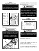
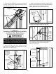
until taut, checking that both cables have equal tension.
(See Fig 11.3)
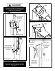
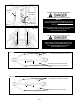
STEP 12
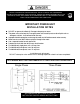
(Installing Overhead Microswitch)
1. Install the overhead Microswitch as shown below. Be
sure to keep wire clear of moving parts. (See Fig.12.1)
Note: Second Microswitch for 3 phase wired units ONLY.
3 phase Microswitch Kit can be found in the Power Unit
shipping box.
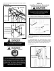
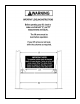
2. Route Microswitch wire though the hole in Power
Side post with a rubber grommet. Loosely position Power
Side safety cover and run other end of Microswitch wire
through hole with grommet in Power Side safety cover.
(See Fig. 12.2)
Fig. 11.3
Nylock
Nut
Threaded
Cable End
Threaded cable
end comes down
from Overhead
Assembly and
into hole on top of
the carriage plate.
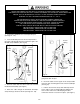
ALL WIRING MUST BE PERFORMED
BY A LICENSED ELECTRICIAN.
DO NOT PERFORM ANY MAINTENANCE OR
INSTALLATION OF ANY COMPONENTS WITHOUT
FIRST ENSURING THAT ELECTRICAL POWER HAS
BEEN DISCONNECTED AT THE SOURCE OR AT
POWER PANEL AND CANNOT BE RE-ENERGIZED
UNTIL ALL MAINTENANCE AND/OR INSTALLATION
PROCEDURES ARE COMPLETED.
MICROSWITCH WIRE MUST BE RUN THROUGH
CLIPS IN POST AND OVERHEAD ASSEMBLY.
FAILURE TO DO SO CAN CAUSE DAMAGE
TO LIFT OR TO VEHICLES.
Fig. 12.1
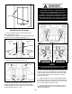
Fig. 11.2
XPR-10AS
Short Cable
Here
Equalizer Cables
Sheave
Brackets
Sheaves
Fig. 12.2
Route Microswitch
wire thought holes
with grommets
Power Side
safety cover
Microswitch
Microswitch
Box
CoverCover