
Product Manual


26
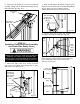
STEP 14
(Installing the Lift Arms)
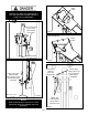
1. Place the appropriate lift arm assembly in the lift
heads. (See Fig. 14.7 - 14.8)
2. Install the lift head pins into the lift head and through
the holes in the arm assembly. (See Fig. 14.1)
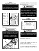
3. Install the snap ring into the groove in the lift head pin
on under side of the lift head. (See Fig. 14.2)
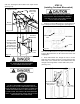
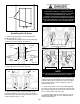
4. Each arm restraint gear can be oriented in a Left
or Right conguration on the arms. Each arm and arm
restraint gear must be positioned in the proper location in
the lift head. (See Fig. 14.3 - 14.4)
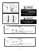
5. Place each Gear Ring against the Lift Head Pin and
align the holes in the Gear Ring with the threaded holes
in the Arm Ears. Ensure that the teeth on the Gear Ring
mesh smoothly with the teeth on the gears of the Lift
Head. (See Fig. 14.5)
6. Verify the operation of the arm restraints by pulling
up on the key ring of the arm restraint pin. Pivot the arms
back and forth and test the operation of the arm restraint
pin in various positions. (See Fig. 14.6)
7. Ensure that the arms do not move when a force of
approximately 100 pounds or less is applied laterally to
the fully extended arms.
26
Fig. 13.5
Screw
NOTE:
LEFT AND RIGHT ARE DETERMINED WHEN FACING
THE INSIDE/OPEN SIDE OF THE LIFT POST.
Lift Head
Pin
Lift Head
Pin
Snap
Ring
Snap
Ring
Lift Head
Fig. 14.1
Fig. 14.2
Lift Head
Pin
Lift Head
Pin
Snap
Ring
Fig. 14.3
Fig. 14.4
LEFT RIGHT
NOTE: Arm gears rings have
Left and Right orientations
THE ARM RESTRAINT GEARS MUST BE
POSITIONED PROPERLY. CONFIRMATION OF
PROPER GEAR ENGAGEMENT MUST BE MADE
PRIOR TO THE OPERATION OF THE LIFT.
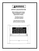
PERIODIC INSPECTION IS REQUIRED. FAILURE
TO INSPECT THE ARM RESTRAINT GEARS ON ALL
FOUR ARMS PROPERLY CAN RESULT IN DAMAGE
TO THE VEHICLE OR INJURY AND/OR DEATH.