
Product Manual


3333
POST-INSTALLATION CHECK-OFF
n Columns properly shimmed and stable.
n Anchor Bolts tightened.
n Pivot / Sheave Pins properly attached.
n Electric power supply conrmed.
n Cables adjusted properly.
n Safety Locks functioning properly.
n Check for hydraulic leaks.
n Oil level.
n Lubrication of critical components.
n Check for overhead obstructions.
n All Screws, Bolts, and Pins securely fastened.
n Surrounding area clean.
n Operation, Maintenance and Safety Manuals
on site.
n Perform an Operational Test with a typical vehicle.
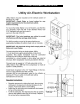
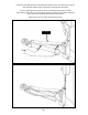
STEP 17
(Lubrication)
1. After installation and start-up have been completed,
lubricate lift components as described below.
(See Fig. 17.1)
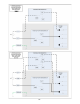
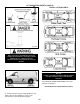
STEP 18
(Bleeding the Cylinders)
1. After electrical power is connected and oil reservoir
is full, press button to raise lift.
2. Continue raising until lift cylinders extend to full
height. DON’T continue pressing button after lift reaches
full height. Damage to the motor can occur if continued.
3. Lower the lift only HALF WAY by pressing the
SAFETY RELEASE handle inward then pressing the
DOWN lever on the power unit.
4. With the lift at half height, slowly loosen the BLEED
SCREWS located at the top of each cylinder to bleed
trapped air. DO NOT completely remove bleed screws.
Re-tighten after trapped air has escaped. (See Fig. 18.1)
5. Lower the lift completely by pressing the SAFETY
RELEASE handle inward then pressing the DOWN lever
on power unit. Wait ve minutes and repeat bleeding
process one additional time.
THE LIFT WILL MOVE DOWN WHEN BLEEDING
MAKE SURE ALL EQUIPMENT, PERSONNEL, HANDS
AND FEET ARE CLEAR FROM THE AREA.
Fig. 18.1
Fig. 17.1
Cylinder
Bleed
Screw
DO NOT
completely
remove
Bleed Screw.
One full turn
should purge
trapped air.
NOTE:
THERE WILL BE INITIAL STRETCHING OF THE
CABLES AND/OR WITH INCREASED LOADS.
ADJUST THE CABLES AS OUTLINED ABOVE A
WEEK AFTER FIRST USE, THEN EVERY THREE
TO SIX MONTHS THEREAFTER DEPENDING ON
USAGE AND/OR TO COMPENSATE FOR STRETCH.