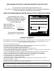
IMPORTANT SAFETY INSTRUCTIONS SAVE THESE INSTRUCTIONS EUROPEAN USERS 400V 50Hz SUPPLY DETAILS ARE INCLUDED WITH ELECTRICAL CONTROL BOX. DISREGARD SUPPLY WIRING DETAILS IN THIS MANUAL PLEASE READ THE ENTIRE CONTENTS OF THIS MANUAL PRIOR TO INSTALLATION AND OPERATION. BY PROCEEDING WITH LIFT INSTALLATION AND OPERATION YOU AGREE THAT YOU FULLY UNDERSTAND AND COMPREHEND THE FULL CONTENTS OF THIS MANUAL. FORWARD THIS MANUAL TO ALL OPERATORS.
9,000 LB/4082 KG CAPACITY SURFACE MOUNTED TWO-POST LIFTS This instruction manual has been prepared especially for you. Your new lift is the product of over 40 years of continuous research, testing and development; it is the most technically advanced lift on the market today. READ THIS ENTIRE MANUAL BEFORE INSTALLATION & OPERATION BEGINS. Santa Paula, CA USA www.bendpak.
OWNER’S RESPONSIBILITY IMPORTANT NOTICE To maintain the lift and user safety, the responsibility of the owner is to read and follow these instructions: Do not attempt to install this lift if you have never been trained on basic automotive lift installation procedures. Never attempt to lift components without proper lifting tools such as forklift or cranes. Stay clear of any moving parts that can fall and cause injury.
TABLE OF CONTENTS Warranty / Serial Number Information . . . . . . . . . . . . . . . . . . . . . . . . . . . . . . . . . . . . . . . . . . . . . . . . . . . . . . . . . . . . . . 2 Definitions of Hazard Levels . . . . . . . . . . . . . . . . . . . . . . . . . . . . . . . . . . . . . . . . . . . . . . . . . . . . . . . . . . . . . . . . . . . . . . 3 Owner’s Responsibility . . . . . . . . . . . . . . . . . . . . . . . . . . . . . . . . . . . . . . . . . . . . . . . . . . . . . . . . . . . . . . . . . . . .
INSTALLER / OPERATOR PLEASE READ AND FULLY UNDERSTAND. BY PROCEEDING YOU AGREE TO THE FOLLOWING: Please read entire manual prior to installation. Do not operate this machine until you read and understand all the dangers, warnings and cautions in this manual. For additional copies or further information, contact: t I have visually inspected the site where the lift is to be installed and verified the concrete to be in good condition and free of cracks or other defects.
INTRODUCTION 1. Carefully remove the crating and packing materials. CAUTION! Be careful when cutting steel banding material as items may become loose and fall causing personal harm or injury. 2. Check the voltage, phase, and proper amperage requirements for the motor shown on the motor plate. Electrical work should be performed only by a certified electrician. IMPORTANT SAFETY INSTRUCTIONS Read these safety instructions entirely.
TOOLS REQUIRED t t t t t t t Rotary Hammer Drill or Similar 3/4” Masonry Bit Hammer 4 Foot Level Open-End Wrench Set: SAE/Metric Socket And Ratchet Set: SAE/Metric Hex-Key / Allen Wrench Set t t t t t t t Large Crescent Wrench Large Pipe Wrench Crow Bar Chalk Line Medium Flat Screwdriver Tape Measure: 25 Foot Minimum Needle Nose Pliers IMPORTANT NOTICE These instructions must be followed to ensure proper installation and operation of your lift.
When removing the lift from shipping angles, pay close attention as the posts can slide and can cause injury. Prior to removing the bolts make sure the posts are held securely by a fork lift or some other heavy lifting device. PARTS INVENTORY Be sure to take a complete inventory of parts prior to beginning installation.
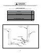
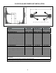
FLOOR PLAN AND POWER UNIT INSTALLATION MODEL XPR-9S XPR-9S-LP XPR-9TS Lifting Capacity 9,000 lbs." / 4082 kg. 9,000 lbs.” / 4082 kg. 9,000 lbs." / 4082 kg. *Max Capacity/ Front Axle 4,500 lbs." / 2041 kg. 4,500 lbs.” / 2041 kg. 4,500 lbs." / 2041 kg. *Max Capacity/ Rear Axle 4,500 lbs." / 2041 kg. 4,500 lbs.” / 2041 kg. 4,500 lbs." / 2041 kg. A -Height Overall; (*) 113” / 2870 mm. 113” / 2870 mm. 113” / 2870 mm. B -Width Overall -NARROW CONFIGURATION 132" / 3353 mm. 132” / 3353 mm.
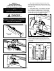
STEP 3 (Post Preparation) 1. With the post assemblies laying on the floor, slide the lift head up towards the top of the post. Inspect and ensure all socket head cap screws and hex nuts are tight. (See Fig 3.1 - 3.3) NOTE: 2. Install cylinder fittings. First install the 90° 3/8” Fitting into the cylinder port using teflon tape on the pipe threads. Next, assemble the tube fitting and 3/8” to 1/4” Hose Fitting together. Again, use teflon tape on all pipe threads.
Fig 3.8 NOTE FOR XPR-9S MODELS: FOR NARROW CONFIGURATION USE THE BUTTON LOCATED AT 12” ABOVE CABLE END. FOR WIDE CONFIGURATION USE THE BUTTON LOCATED ON THE END OF THE CABLE. Towards Top Plate Sheave 4. Identify the correct cable button on the end of each equalizer cable that corresponds to your desired lift configuration. (See Fig 3.6) Secure the correct cable button at the lift head lock plate located inside each lift head. Fig 3.
9. Uncoil cable and route cable around the Top Plate sheave and coil the remaining cable up and leave it in the post above the lift head. (See Fig 3.13) Fig 3.10 M10 Bolt M10 Spring Lock Washer Fig 3.13 M10 Nut 8. Slide lift head back towards the base plate. Ensure the lift head chain is properly positioned with the lift head chain sheave. (See Fig 3.11) Failure to properly align lift head chain and/or cylinder will result in lift malfunction. Fig 3.
SITE LAYOUT / FLOOR PLAN A Model XPR-9S XPR-9S Configuration Narrow Wide A 3353 mm / 132” 3683 mm / 145” STEP 4 (Site Layout) Capacity 9,000 LBS/4082 KG 9,000 LBS/4082 KG 4. Once a location is determined, use a carpenters chalk line to layout a grid for the post locations. Keep all dimensions square within 1/8” (3mm) or malfunctioning of the lift can occur. 1. Determine which side of the lift will be the approach side. 2. Now determine where the power unit will be located.
CLEARANCES XPR-9S NOTE: SUBTRACT 6-1/2” FROM MINIMUM NEAREST WALL AND MINIMUM NEAREST BAY DIMENSION FOR NARROW CONFIGURATION. APPROACH LIFT HEIGHT CLEARANCE NOTE: There must be 75” plus he height of typical vehicle MIN distance from top of lift to nearest obstruction. NOTE: Lift measurements shown in WIDE configuration STEP 5 (Installing the POWER SIDE post) 4. Assemble the washers and nuts on the anchors then tap into each hole with a hammer until the washer rests against the base plate.
5. If shimming is required, insert the shims as necessary under the base plate so that when the anchor bolts are tightened, the posts will be plumb. (See Fig. 5.3) Fig 7.1. Vibration Dampener M8 x1.25 x 35mm hex head bolts, M8 flat washers and M8 Nylock nuts (Qty 4 ea) Fig 5.3 6. With the foot guards, shims and anchor bolts in place, tighten by securing the nut to the base then turning 3-5 full turns clockwise (90 ft-lbs.). DO NOT use an impact wrench for this procedure. (See Fig. 5.4) 2.
DO NOT RUN POWER UNIT WITHOUT OIL. DAMAGE TO POWER UNIT PUMP CAN OCCUR. THE POWER UNIT MUST BE KEPT DRY. DAMAGE TO POWER UNIT CAUSED BY WATER OR OTHER LIQUIDS SUCH AS DETERGENTS, ACID ETC., IS NOT COVERED UNDER WARRANTY. OPERATE LIFT ONLY BETWEEN TEMPERATURES OF 41 °- 104° F. IMPROPER ELECTRICAL HOOK-UP CAN DAMAGE MOTOR AND WILL NOT BE COVERED UNDER WARRANTY. MOTOR CAN NOT RUN ON 50HZ WITHOUT A PHYSICAL CHANGE IN THE MOTOR. USE A SEPARATE CIRCUIT BREAKER FOR EACH POWER UNIT.
3. Route the cable over the sheave and route it towards the baseplate safety sheave. (See Fig 8.5) Fig 8.7 Safety Cable ENSURE THAT BOTH THE POWER SIDE & OFF SIDE SAFETIES ENGAGE PROPERLY PRIOR TO LIFT OPERATION. Fig 8.5 From Off Side Post Route safety cable over Off Side safety sheave and down towards base plate NOTE: Post and lift head cut away for clarity 7. Pull the slack out the safety cable and keep tension on the cable as nuts are being tightened.
ENSURE THAT BOTH THE POWER SIDE & OFF SIDE SAFETIES ENGAGE PROPERLY PRIOR TO LIFT OPERATION. WHEN ROUTING HYDRAULIC HOSES THROUGH THE POSTS, ROUTE HOSES THROUGH THE HOSE CLIPS WELDED ON EACH POST. MAKE SURE THAT THE HOSE IS CLEAR OF ANY MOVING PARTS. IT MAY BE NECESSARY TO TIE THE HOSES CLEAR BY USING NYLON TIE STRAPS OR WIRE. FAILURE TO KEEP THE HYDRAULIC HOSES CLEAR MAY RESULT IN THE HYDRAULIC HOSES TO FAIL, WHICH MAY RESULT IN DAMAGE OR PERSONAL HARM. Fig 8.9 Fig 9.
STEP 10 (Routing the Equalizer Cables) WHEN THE CABLE ADJUSTING NUTS BOTTOM OUT 1. Raise and lock each lift head approximately 28” above the ground. (See Fig. 10.1) ON THE THREADED END OF THE CABLE CONNECTOR AND THERE IS STILL SLACK IN THE CABLES, THE CABLES HAVE STRETCHED BEYOND Fig 10.1 THE SAFE USEFUL LENGTH AND NEED TO BE REPLACED WITH FACTORY APPROVED CABLE ASSEMBLIES.
STEP 11 (Installing power unit hose assembly and Power Side safety cover) 2. With the lift heads locked at 28” off the floor, uncoil the equalizer cables and route the threaded end of the equalizer cables towards the Base Plate sheave. Wrap the cable around the base plate sheave and reinstall sheave. (See Fig. 10.2) 1. After safeties have been adjusted and checked for proper operation, install and tighten Power Side safety cover and Off Side safety cover mounting screws. (See Fig. 11.1) Fig 10.
NOTE: Lift Head Pin LEFT AND RIGHT ARE DETERMINED WHEN FACING THE INSIDE. OPEN SIDE OF THE LIFT POST. Lift Head Pin Lift Head Snap Ring Snap Ring Fig. 12.1 Lift Head Pin Lift Head Pin NOTE: Arm gears rings have Fig 12.3 Left and Right orientations 4. Each arm restraint gear can be oriented in a Left or Right configuration on the arms. Each arm and arm restraint gear must be positioned in the proper location in the lift head. (See Fig. 12.4 & 12.5) Fig. 12.4 Snap Ring Fig. 12.
Lift Head Pin Arm Restraint Gear Ring YOU MUST INSTALL POST TIE ROD (AS SHOWN) TIGHTEN POST TIE ROD TO 2-3 FT.-LB. OF TORQUE UPON FINAL INSTALLATION INSPECTION. THESE INSTRUCTIONS MUST BE FOLLOWED TO ENSURE PROPER INSTALLATION AND OPERATION OF YOUR LIFT. FAILURE TO COMPLY WITH THESE INSTRUCTIONS CAN RESULT IN SERIOUS BODILY INJURY AND/OR DEATH AND/OR VOID PRODUCT WARRANTY.
POWER-UNIT CONNECTION DO NOT PERFORM ANY MAINTENANCE OR INSTALLATION OF ANY COMPONENTS WITHOUT FIRST ENSURING THAT ELECTRICAL POWER HAS BEEN DISCONNECTED AT THE SOURCE OR PANEL AND CANNOT BE RE-ENERGIZED UNTIL ALL MAINTENANCE AND/OR INSTALLATION PROCEDURES ARE COMPLETED. IMPORTANT POWER-UNIT INSTALLATION NOTES n DO NOT run power unit without oil. Damage to pump can occur. n The power unit must be kept dry. Damage to power unit caused by water or other liquids such as detergents, n n n n n n n acid etc.
POWER-UNIT CONNECTION ALL WIRING MUST BE PERFORMED BY A CERTIFIED ELECTRICIAN ONLY. SEE WIRING INSTRUCTIONS AFFIXED TO MOTOR FOR PROPER WIRING INSTRUCTIONS. SINGLE PHASE 208-230V, 60Hz, 30 Amps Line 1 Black Line 2 White Green Ground EQUIP GR G L N L6-30R plug *Special Voltages Available Upon Request. 25 Guard against electric shock. Never connect the green power cord wire to a live terminal. This is for ground only.
STEP 13 (Power Unit Connection) STEP 14 (Lift Start Up / Final Adjustments) 1. Have a certified electrician run the power supply to motor. Refer to the data plate found on the motor for proper power supply and wire size. DURING THE START-UP PROCEDURE, OBSERVE ALL OPERATING COMPONENTS AND CHECK FOR PROPER INSTALLATION AND ADJUSTMENT. DO NOT ATTEMPT RISK OF EXPLOSION! TO RAISE VEHICLE UNTIL A THOROUGH OPERATIONAL CHECK HAS BEEN COMPLETED.
POST-INSTALLATION CHECK-OFF NOTE: THERE WILL BE INITIAL STRETCHING OF THE CABLES AND/OR WITH INCREASED LOADS. ADJUST THE CABLES AS OUTLINED ABOVE A WEEK AFTER FIRST USE, THEN EVERY THREE TO SIX MONTHS THEREAFTER DEPENDING ON USAGE AND/OR TO COMPENSATE FOR STRETCH.
• Shall display the lift manufacturer’s operating instructions; ALI/SM 93-1, ALI Lifting It Right safety manual; ALI/ST-90 ALI Safety Tips card; ANSI/ALI ALOIM-2000, American National Standard for Automotive Lifts-Safety Requirements for Operation, Inspection and Maintenance; and in the case of frame engaging lifts, ALI/ LP-GUIDE, Vehicle Lifting Points/Quick Reference Guide for Frame Engaging Lifts; in a conspicuous location in the lift area convenient to the operator. either being raised or lowered.
• DO NOT remove or disable arm restraints. LIFT OPERATION SAFETY • ALWAYS remain clear of lift when raising or lowering vehicles. 1. Before Loading: Lift must be fully lowered and service bay clear of all personnel before the vehicle is brought on lift with the swing arms set to the full drive-thru position. • ALWAYS use safety stands when removing or installing heavy components. 2. Loading: Swing arms under vehicle and position adapters at vehicle manufacturer’s recommended lift points.
LIFT OPERATION SAFETY (CONT’D) 4. Position vehicle for proper weight distribution arms under vehicle to allow adapters to contact at the manufacturer’s recommended pick up points. 6. Push the RAISE button or rotate the control switch on the power unit. NOTE: ALLOW (2) SECONDS BETWEEN MOTOR STARTS. FAILURE TO COMPLY MAY CAUSE MOTOR BURNOUT. 7. Stop before making contact with vehicle. Check arm restraint pins for engagement. If required, slightly move arm to allow restraint gear and pawl to mesh.
t t t t LIFT OPERATION SAFETY (CONT’D) Vehicle individual axle weight does not exceed one-half lift capacity. Adapters are in secure contact with frame at vehicle manufacturers recommended lift points. Vehicle is stable on lift and the center of gravity is NOT off balance. The overhead switch bar will contact the highest point on the vehicle. WHEN LOWERING THE LIFT PAY CAREFUL ATTENTION THAT ALL PERSONNEL AND OBJECTS ARE KEPT CLEAR.
LIFT OPERATION SAFETY (CONT’D) Before lifting the vehicle, make sure it is neither front nor rear heavy. See image below. Center of balance should be midway between adapters.
OPTIONAL AND STANDARD ACCESSORIES Optional Equipment available through your Authorized BendPak Dealer.
If the lift was provided with Lift Arm Foot Guards, install the shorter Foot Guard on the shorter Arm Assembly and the longer Foot Guard on the longer Arm Assembly. To install firmly squeeze the ends of the Foot Guard inwards and insert the ends underneath the bent ends of the arm support. Release to allow the Foot Guard to spring into place. Check to be sure that Foot Guard is firmly in place. Repeat this step for each Arm Assembly Foot Guard.
OPTIONAL EQUIPMENT INSTALLATION 35
TO RAISE LIFT t t Read operating and safety manuals before using lift. Always lift a vehicle according to the manufacturers recommended lifting points. Position vehicle between posts. Adjust swing arms so that the vehicle is positioned with the center of gravity midway between pads. Use truck adapters as needed. Never exceed 9” of pad height. NEVER use lift pad assemblies without rubber slip over pads in place. Raise the vehicle by depressing button until the vehicle just lifts off the ground.
WIRE ROPE INSPECTION AND MAINTENANCE t Lifting cables should be replaced every three - five years or when visible signs of damage are apparent. DO NOT USE LIFT WITH DEFECTIVE / WORN CABLES. t Lifting cables should be maintained in a well-lubricated condition at all times. Wire rope is only fully protected when each wire strand is lubricated both internal and external. Excessive wear will shorten the life of the wire rope.
Safe Lift Operation Automotive and truck lifts are critical to the operation and profitability of your business. The safe use of this and other lifts in your shop is critical in preventing employee injuries and damage to customer’s vehicles. By operating lifts safely you can ensure that your shop is profitable, productive and safe. Safe operation of automotive lifts requires that only trained employees should be allowed to use the lift.
t DO NOT leave the controls while the lift is still in motion. t DO NOT stand directly in front of the vehicle or in the bay when vehicle is being loaded or driven into position. t DO NOT go near vehicle or attempt to work on the vehicle when being raised or lowered. t REMAIN CLEAR of lift when raising or lowering vehicle. t DO NOT rock the vehicle while on the lift or remove any heavy component from vehicle that may cause excessive weight shift.
LIFT WILL NOT RAISE POSSIBLE CAUSE 1. Air in oil, (1,2,8,13) 2. Cylinder binding, (9) 3. Cylinder leaks internally, (9) 4. Motor run backward under pressure, (11) 5. Lowering valve leaks, (3,4,6,10,11) 6. Motor runs backwards, (7,14,11) 7. Pump damaged, (10,11) 8. Pump won’t prime, (1,8,13,14,3,12,10,11) 9. Relief valve leaks, (10,11) 10. Voltage to motor incorrect, (7,14,11) REMEDY INSTRUCTION 1. Check for proper oil level. . . . . . . . . . . . . . . . . . . . . . . . . .
MOTOR WILL NOT RUN POSSIBLE CAUSE 1. Fuse blown, (5,2,1,3,4) 2. Limit switch burned out, (1,2,3,4) 3. Microswitch burned out, (1,2,3,4) 4. Motor burned out, (1,2,3,4,6) 5. Voltage to motor incorrect, (2,1,8) REMEDY INSTRUCTION 1. Check for correct voltage . . . . . . . . . . . . . . . . . . . . . . . . . . .Compare supply voltage with voltage on motor name tag. Check that the wire is sized correctly. N.E.C. table 310-12 requires AWG 10 for 25 Amps. 2. Check motor is wired correctly . . . .
WILL NOT RAISE LOADED LIFT POSSIBLE CAUSE 1. Air in oil, (1,2,3,4) 2. Cylinder binding, (5) 3. Cylinder leaks internally, (5) 4. Lift overloaded, (6,5) 5. Lowering valve leaks, (7,8,1,5,9) 6. Motor runs backwards, (10,12,9) 7. Pump damaged, (5,9) 8. Pump won’t prime, (1,2,3,4,5,11,9) 9. Relief valve leaks, (8,5,9) 10. Voltage to motor incorrect, (10,12,5) REMEDY INSTRUCTION 1. Check oil level . . . . . . . . . . . . . . . . . . . . . . . . . . . . . . . . . .
LIFT WILL NOT STAY UP POSSIBLE CAUSE 1. Air in oil, (1,2,3) 2. Check valve leaks, (6) 3. Cylinders leak internally, (7) 4. Lowering valve leaks, (4,5,1,7,6) 5. Leaking fittings, (8) REMEDY 1. Check oil level . . . . . . . . . . . . . . . . . . . . . . . . . INSTRUCTION The oil level should be up to the bleed screw in the reservoir with the lift all the way down. 2. Oil seal damaged and cocked . . . . . . . . . . . . . . . . . . . . . Replace oil seal around pump shaft. 3. Bleed cylinder . . . . . .
MAINTENANCE RECORDS ____________________________________________________________________ ____________________________________________________________________ ____________________________________________________________________ ____________________________________________________________________ ____________________________________________________________________ ____________________________________________________________________ ____________________________________________________________________ _________
1. 2. 2 A 6 SEE SHIPPING INSTRUCTIONS FOR FINAL PACKAGING ALL LABELS TO BE APPLIED TO POSTS AFTER PAINTING. SEE ATTACHED LABEL PLACEMENT SHEET. NOTE: UNLESS OTHERWISE SPECIFIED. 3 1 4 5215226 5905109 5905131 5905402 5905465 5905650 5905940 5905950 4 5 6 7 8 9 10 11 DIMENSIONS ARE IN MM ☺ DESCRIPTION DETAIL A SCALE 1 : 12 9 11 8 02/24/2016 CA PROPRIETARY AND CONFIDENTIAL THE INFORMATION CONTAINED IN THIS DRAWING IS THE SOLE PROPERTY OF BENDPAK INC.
3 1 2 1. 2. A SEE SHIPPING INSTRUCTIONS FOR FINAL PACKAGING ALL LABELS TO BE APPLIED TO POSTS AFTER PAINTING. SEE ATTACHED LABEL PLACEMENT SHEET. NOTE: UNLESS OTHERWISE SPECIFIED.
1. 5 3 SEE SHIPPING INSTRUCTIONS FOR FINAL PACKAGING NOTE: UNLESS OTHERWISE SPECIFIED. 4 2 NEXT ASSEMBLY 5260553 5260558 5260557 1 DIMENSIONS ARE IN MM ☺ DO NOT SCALE DRAWING PROPRIETARY AND CONFIDENTIAL THE INFORMATION CONTAINED IN THIS DRAWING IS THE SOLE PROPERTY OF BENDPAK INC. ANY REPRODUCTION IN PART OR AS A WHOLE WITHOUT THE WRITTEN PERMISSION OF BENDPAK INC. IS PROHIBITED.
2 SEE SHIPPING INSTRUCTIONS FOR FINAL PACKAGING ALL LABELS TO BE APPLIED TO POSTS AFTER PAINTING. SEE ATTACHED LABEL PLACEMENT SHEET. NOTE: UNLESS OTHERWISE SPECIFIED. 1. 2. 12 3 1 A 6 5215226 5905109 5905131 5905402 5905465 5905650 5905940 5905950 5215700 4 5 6 7 8 9 10 11 12 DIMENSIONS ARE IN MM ☺ 5 DETAIL A SCALE 1 : 12 DESCRIPTION 7 9 8 11 PROPRIETARY AND CONFIDENTIAL THE INFORMATION CONTAINED IN THIS DRAWING IS THE SOLE PROPERTY OF BENDPAK INC.
1. 2. 3. 4. SEE SHIPPING INSTRUCTIONS FOR FINAL PACKAGING INSERT PARTS BAG INTO PARTS BOX FOR SHIPMENT THREAD 5535358 WITH 5545342 ONTO CABLES FOR SHIPMENT HOSES AND CABLES IN REPRESENTATIONAL FORM NOTE: UNLESS OTHERWISE SPECIFIED. NEXT ASSEMBLY 5260553 5260558 5260557 ☺ DIMENSIONS ARE IN MM PROPRIETARY AND CONFIDENTIAL THE INFORMATION CONTAINED IN THIS DRAWING IS THE SOLE PROPERTY OF BENDPAK INC. ANY REPRODUCTION IN PART OR AS A WHOLE WITHOUT THE WRITTEN PERMISSION OF BENDPAK INC. IS PROHIBITED.
1. A 17 DETAIL C SCALE 1 : 5 DETAIL A SCALE 1 : 5 4 5 3 1 SEE SHIPPING INSTRUCTIONS FOR FINAL PACKAGING NOTE: UNLESS OTHERWISE SPECIFIED. B 2 20 C 19 NEXT ASSEMBLY 5250037 18 14 9 DIMENSIONS ARE IN MM ☺ DO NOT SCALE DRAWING 8 11 10 15 7 05/30/2014 10/06/2014 12/17/2015 06/17/2013 DATE TM TM TM TM 02/19/2016 CA PROPRIETARY AND CONFIDENTIAL THE INFORMATION CONTAINED IN THIS DRAWING IS THE SOLE PROPERTY OF BENDPAK INC.
Declaration of Conformity The equipment which accompanies this declaration is in conformity with EU Directive: 2006/42/EC Machinery Directive Manufacturer Bendpak Inc. 1645 Lemonwood Dr Santa Paula Ca, 93060 USA A copy of the Technical file for this equipment is available from: CCQS UK Ltd., Level 7, Westgate House, Westgate Rd., London W5 1YY UK Description of Equipment Two-Column Vehicle Service Lift XPR-9S/ 9K 4082 kg (9000 lb) capac.