CE30-A Solid State Array LiDAR Specification Benewake (Beijing) Co., Ltd.
Table of Contents 1. 2. 3. 4. 5. 6. 7. Page 2 Product Overview.................................................................................................................................................. 3 Principle of Ranging ............................................................................................................................................. 4 Description of Obstacle Avoidance Mode .............................................................................................
1. Product Overview Figure 1 CE30-A Characteristics Complete solid-state design Area-array detection Horizontal FOV > 120° Vertical FOV 9° ROI setting for obstacle avoidance mode Embedded algorithm: nearest obstacle calculation, transferred by CAN BUS Table 1 CE30-A Specification Parameter1 Typical Value Method Time of flight Peak Wavelength 850nm FOV2 132*9 degree Pixel Resolution 320*24 Frame Rate 20fps Ranging Resolution 1cm Detecting Range3 0.
Repeatability(1σ) ≤3cm Accuracy ≤6cm Ambient Light Resistance4 60klux Data Interface CAN Operating Temperature 0~50℃ Storage Temperature -30~70℃ Supply Voltage DC 12 V±5%(≥2A) Power Consumption ≤6W Dimensions 79*47*50mm Enclosure Rating IP65 Eye Safety Class EN 62471 Exempt Weight 219g 2. 5 Principle of Ranging The ranging principle of CE30-A is based on Time of Flight (TOF).
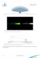
Figure 3 Illustration of CE30-A detection area. Compared with single-channel LiDAR, CE30-A has a wider vertical FOV. Figure 4 A real detected scene. Depth image (left) and corresponding grey image (right). In practical use, some cylindrical objects can be clearly captured (such as table leg). Figure 5 Application in the obstacle avoidance mode. Compared with the 2D Scanning LiDAR (the red line), CE30-A can detect obstacles lower than the mounting height.
Figure 6 Illustration of Detecting Range and Area The farthest detecting range of each angle has been optimized for general obstacle avoidance scenarios, which are different from regular detecting range. The schematic diagram is shown in Figure 6 (Customization is available for special requirements). Figure 7 Optimized Detecting Area for Obstacle Avoidance Application 3. Description of Obstacle Avoidance Mode 3.1.
The principle of the obstacle selection is as follows: CE30-A selects the nearest obstacle to LiDAR. Then it gathers detecting and computing resources, to calculate the azimuth and the projected distance of the obstacle more precisely.
Figure 10 Schematic of ROI Function Determination 4. Communication Protocol The following sections describe the communication protocol between CE30-A and external devices. The interface supports Ethernet/TCP protocol and CAN bus. Currently only the CAN bus protocol is available for the obstacle avoidance mode. 4.1. CAN Bus (Obstacle Avoidance Mode) CE30-A uses CAN standard frame, with default baud rate 250kbps. 4.1.1.
operation mode, the command does not take effect and the machine will be restored to the state before center calibration. ) 1) Depth is the ROI length of the test distance, in dm; 2) Width is half the ROI width of the test distance, in cm; 3) The Spare field is temporarily reserved. 4.1.2. Data Frame Format Table 3 CAN Data Frame Format CE30-A-->MPU Data length Description 2 Little-endian.
bit3: reserve bit4: 1 – Center calibrated; 0 – Without center calibration; bit5_7: Heartbeat value (From 0 to 7 in turn) Version number 2 Version number The time interval of the heartbeat packet is 150ms. If there is a version inquiry, the heartbeat packet (including the version number) will respond immediately. 4.1.4. Baud Rate & ID Configuration Format MPU-->CE30 Byte length Description Data ID 1.5(byte0+byte1:0-3bit) Data frame ID,little-endian Heartbeat ID 1.
1. Shell 2. Receiving panel (working area, no coving) 3. Sending panel (working area, no coving) 4. Power supply/CANBUS (M8 aerial socket) 5. Ethernet port (M8 aerial socket) 6. Equipment installing hole (M3) Figure 11 Structure and Dimension of DELiDAR CE30-A 6. Aerial Socket Interface Description Female: Ethernet connector - aerial socket with 8 mm diameter. Male: Power supply/CANBUS connector - aerial socket with 8 mm diameter.
Figure 13 Power Supply/CANBUS Socket Pin Definition Pin number Explanation 1 ETH_RX_P 2 ETH_RX_N 3 ETH_TX_P 4 ETH_TX_N Figure 14 Ethernet Socket Pin Definition 7.