A DIVISION OF W.R. BENJAMIN PRODUCTS LIMITED HEATING PRODUCTS OWNERS MANUAL MODEL CC500 IS CERTIFIED TO: 1 CSA B140.7.1 CAN/CSA B366.1 UL391 UL726 Unit Serial # Burner Serial # Purchased From Company Address Name of Installer Installer Telephone # Date Installed IMPORTANT This manual must be given to the homeowner. Please read the warranty and return the warranty card to initiate coverage. We Strongly Recommend The Use Of A Carbon Monoxide Detector When Using Any Product That Consumes Fossil Fuels.
KEEP THIS MANUAL FOR FUTURE REFERENCE. Follow all instructions carefully for installation, maintenance & operation of the CC500 boiler. TABLE OF CONTENTS 1. 2. 3. 4. 5. 6. 7. 8. 9. 10. 11. 12. 13.
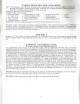
TAKING DELIVERY AND UNPACKING Note: The consignee is responsible for ensuring that the packages have arrived in good condition. Examine the packages for damages, if found, note the same on carriers' bill of lading and make a claim to the carrier. Each unit is carefully inspected before leaving our factory.
PLACEMENT OF THE UNIT The CC500 should be as close to the chimney as possible. The CC500 can be installed on a COMBUSTIBLE floor using a non-combustible pad extending 20" front and rear and 6" on each side. The boiler must be properly LEVELED. A 1" (2.5cm) minimum air space must be maintained under the appliance. This can be achieved by using four non-combustible blocks, a minimum of 1" (2.5cm) thick x 4" (10cm) wide x 8" (20cm) long, one to be placed under each corner.
AQUASTAT SETTINGS As shown on the wiring diagram on page 12. Recommendation If Using The Domestic Hot Water Coils In The Boiler When the wood section of your boiler is not in use for an extended period of time, change the oil aquastat setting to a low limit of 1 SOT and a high limit, not to exceed 200°F. This is to better assist in the heating of the domestic hot water. CAUTION: Be sure to return the settings to the normal (low 150°F & high 170°F) before starting your wood section again.
ELECTRICAL Electrical installations must conform to all local and national codes and standards as their jurisdiction may apply. See page 12. PIPING Pining must conform to all local and national codes and standards as their jurisdiction may apply. See pages 11& 13. The dump zone should be your existing largest zone (that has all piping above the boiler.-e.g. Livingroom or master bedroom).
OPERATING INSTRUCTIONS (WOOD SECTION) Proper draft in the wood section will not be achieved until 2" to 3" of ash is built up in the firebox. This can be readily accomplished using softwoods, which creates ash quickly or use clean sand (with "no salt" in it). Caution: DO NOT fire this boiler until all requirements are complete and the operating instructions are fully understood. NOTE: Your oil burner may start even when the wood fire is on. This is caused by large amounts of heat being taken from the unit.
TO START THE BURNER AFTER AN EXTENDED SHUTDOWN 1. The strainer in the pump should be cleaned, and if a filter is installed in the oil line, it should be cleaned and the filter cartridge replaced. 2. The fan and the blower housing should be cleaned and the air filter replaced. 3. The ignition points should be checked and the nozzle cleaned and replaced. 4. Oil the motor. 5. Start the burner by following the instructions under the paragraph, "TO START THE BURNER". 7.
ELECTRICAL POWER FAILURE NOTE: DO NOT operate your appliance, unless your total heating system has been designed and installed to operate properly without electricity. 1. Maintain 1A the normal fire load. 2. The air damper must be manually operated. (DO NOT prop or tie open.) 3. Fire the boiler carefully. Remember you are now on gravity circulation only. It is necessary to manually open the zone valve (if used). Each system is different, extreme care must be used until a safe rate .
CARE OF THE BOILER WHEN NOT IN USE When the boiler is out of service for an extended period of time, carefully and thoroughly clean the smoke pipe, chimney, firebox and any part which has been in contact with hot gases. This is extremely important as rusting and corrosion occur when the boiler is idle. REPLACING THE HOT WATER COILS The rear casing panel of your boiler must be removed to gain access to the hot water coils mounting plates.
CLEANING AND SERVICING (OIL SECTION)continued OIL BURNER The oil burner should be removed at least once each heating season, cleaned and serviced. Also inspect and clean any accumulated soot and debris from the combustion chamber and transfer duct. Inspect and replace the burner gasket if necessary. To be performed by a Qualified Service Technician. OIL FILTER The cartridge should be replaced at least once a year. The filter body should be thoroughly cleaned before installing a new cartridge. 1. 2. 3. 4.
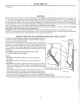
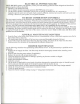
CHIMNEY CONNECTIONS FOR THE CC500 BOILER A LINED MASONRY CHIMNEY APPROVED FOR BURNING SOLID FUEL SAFELY. SMOKE PIPE MUST HAVE A MIN. W PER FOOT RISE FROM THE BOILER TO THE FLUE. AN APPROVED 7" C.S.A. BAROMETRIC DRAFT REGULATOR MAX. FLUE DRAFT SETTING 0.04 INCH W.C. 4" MIN.—^ FACTORY BUILT CHIMNEY APPROVED FOR SOLID FUELS SMOKE PIPE MUST HAVE A MIN. 1/2" PER FOOT RISE FROM THE BOILER TO THE FLUE. WHMK J 4"MIN. CLEANOUT TEE AN APPROVED 7'C.S.A. BAROMETRIC DRAFT REGULATOR MAX. FLUE DRAFT SETTING 0.
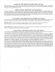
CC500 PIPING & WIRING LAYOUT P2 ;;£"*-3/8 Flexible Metal Conduit PI - Return From System P2 - Cold Water Supply P3 - Supply To System Zones P4 - Mixing Loop 1 - Normally Closed Zone Valve 2 - Air Cushion Tank 3 - Stop Valve 4 - Back Flow Preventer 5 - Pressure Reducing Valve (SetAtl2PSI) 6 - Drain Valve 7 - Pressure Relief Valve (Pipe To A Safe Drain) 8 - Normally Open Zone Valve 9 - Single Aquastat 10 - Line In (120v Power Supply) 11 - Temperature & Pressure Gauge (Indicator) 12 -Triple Aquastat 13 -Da
LINE IN 115 VI 1 760 Hz White ("Neutral) WOOD Triple Aquastat Single Aquastat Damper Motor Low Limn High Limit set20(ff 24 Volt IVansformcr Normally Open Zone Valve MAXIMUM LOAD 30 VA (LOAD 24V) Black OILAqii NOTE: If you are using the domestic coils from the boiler adjust the oil aquastat to LOW-18CHF and HIGH-200"F for the summer months. W.R. Benjamin Products Limited Wiring schematic for CC500 COMBINATION WOOD/OIL BOILER MAY 2006 Burner Control N C Z.V. -- Normally Closed Zone Valve N O Z.V.
DOMESTIC HOT WATER MIXING CIRCULATOR PLUMBING SUGGESTED PLUMBING FOR COILS PRIMARY CIRCULATOR TO HOUSE 1 ViFEED- BALANCE VALVE MIXING CIRCULATOR 1, Cold Water Inlet 2, Shut Off Valve 3, Check Valve 4, Tempering Valve (8" below the coil Outlet) 5, Hot Water To Appliances 6, 120°F Max, Tempered Water to Fixtures 7, Throttle Flow Valve RETURN FROM — HOUSE