
Unit installation
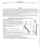
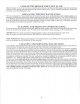


CC500
PIPING
&
WIRING LAYOUT
P2
;;£"*-3/8
Flexible
Metal
Conduit
PI
-
Return
From
System
P2 -
Cold Water
Supply
P3 -
Supply
To
System
Zones
P4 -
Mixing
Loop
1
-
Normally
Closed
Zone
Valve
2 - Air
Cushion Tank
3 -
Stop
Valve
4 -
Back Flow
Preventer
5 -
Pressure
Reducing
Valve
(SetAtl2PSI)
6 -
Drain Valve
7 -
Pressure
Relief Valve
(Pipe
To
A
Safe Drain)
8 -
Normally
Open
Zone
Valve
9 -
Single Aquastat
10
-
Line
In
(120v
Power
Supply)
11
-
Temperature
&
Pressure
Gauge
(Indicator)
12
-Triple
Aquastat
13
-Damper
Motor
14-Wood
Smoke
PipeC
7
"I.
D
15
- 24V
Transformer
16 -
Aquastat Relay (Oil)
17
-
Domestic
Hot
Water
Coil
18 -
Primary Circulator
Pump
19-Oil
Smoke
Pipe(
7"1.D.)
20
Throttle
Valve
W!
"
3
Wire
<
Black
-
whlte
&
Red
>
I2
°
Volt
21
-
Mixing Circulator
Pump'
W2
-
24
Volt
To
Thermostats
&
Zone
Valves
•»•>
-
Blocked
Flue
Sensor
W3
"
24
Volt
Io
Dam
P
er
Motor
22
W4
- 2
Wire
(Black
&
White)
120
Volt
W5
- 2
Wire (Black
&
White)
120
Volt
W6
- 2
Wire
(Black
&
White)
120
Volt
NOTE:
W7
'
2
wire
^
Red
&
Black
>
I2
°
Volt
All
120
Volt,
60 HZ
Wire
Must
Be
16(1
TEW
90'
C,
Encased
In
CSA
or
UL
Certified
3
/&"
Flexible
Metal
Conduit,
using
anti-shorts
in
cable
ends
-11-