
Unit installation


AQUASTAT
SETTINGS
As
shown
on the
wiring diagram
on
page
12.
Recommendation
If
Using
The
Domestic
Hot
Water Coils
In The
Boiler
When
the
wood section
of
your boiler
is not in use for an
extended period
of
time, change
the oil
aquastat
setting
to
a low
limit
of 1
SOT
and a
high limit,
not to
exceed 200°F. This
is to
better assist
in the
heating
of the
domestic
hot
water.
CAUTION:
Be
sure
to
return
the
settings
to the
normal (low
150°F
&
high
170°F)
before starting your
wood section again.
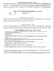
OIL
BURNER
INSTALLATION
Proper
noz/les
and
settings
for
(Use
No. 2
Furnace
OiH:
Burner
Aero
HF-US
Aero HF-US
Beckett
AFG
Beckett
AFG
Riello
F5
Hiello
F5
Nozzle
Delevan 0.85
x
80°B
Delevanl.OOx80°B
Delevan 0.75
x
80°B
Delevan 0.85
x
80°B
Delevan 0.75
x
80°B
Delevan
0.85
x
80°B
Input
0.85
gph
l.OOgph
0.89
gph
1.01
gph
0.90
gph
1
.02
gph
Pump
Pressure
100
psi
100
psi
140
psi
140
psi
145
psi
145
psi
Turbulator
1.5
3.25
Initial
Air
38625
38626
3.5
3.75
BTU/Hour
101200
118300
106600
118700
107000
120700
Insertion
4.00"
4.00"
4.00"
4.00"
4-1/8"
4-1/8"
The oil
burner
is
mounted
on the 3
studs provided
on the
lower
front
combustion chamber access panel. Extreme
care
should
be
taken when mounting
the
burner,
not to
damage
the
molded combustion chamber.
The air
opening
on
the
oil
burner should
be
adjusted
to
obtain
a #0
Bacharach smoke spot.
At
this point, maximum
fuel
efficiency
is
obtained. Having obtained
the
proper smoke spot,
the
following should
be
observed:
The CO in
the
flue
should
be
between
10
and
13.5%.
Draft
setting
- not to
exceed
-.04"
W.C.. (the
draft
is
adjustable
by
means
of
adjusting
the
screw/wheel located
on the
front
of the
barometric
draft
regulator).
INSTALLATION
OF
BLOCKED
FLUE SENSOR
Install
the
Field
Controls
WMO-1
in the oil
flue pipe
as
given
in the
sensor
installation
instructions.
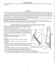
HOW
MUCH
WATER
TO RUN IN THE
SYSTEM
For hot
water heating, beginning with
the
lowest radiator, open
the
vent
and
allow
air to
escape, closing
the
vent
when
the
water begins
to
flow
from
it.
Repeat this
on all
other radiators, continuing
to the
second
and
then higher
floors.
(Radiators equipped with automatic
air
vent valves
do not
require venting
by
hand except
to
speed
up
initial
filling
of
system). Check
the
water level regularly
for
loss
due to
leaks
or
evaporation.
All
systems
must
be
provided
with
an
expansion tank
and
relief valve. Water should
be fed to the
system
by
means
of an
automatic
fill
valve
available
for
that purpose
and
backflow
prevention must
be
used.
The
relief valve should
be
opened
occasionally
to
make sure
it is
operative.
The
relief valve should open when
the
pressure indicated
on the
combination gauge exceeds thirty pounds.
If
this pressure
is
exceeded before
the
relief
valve
opens, shut
off the
fill
valve
and
drain
the
water
from
the
system
until
the
pressure
is
reduced below thirty
pounds
and
have
the
valve repaired
or
replaced immediately.
A
water logged
air
cushion tank
is
indicated
by
rapid
increase
in
pressure with only slight increase
in
temperature,
or
frequent
escape
of
water
from
the
relief valve.
CHECK
THE
SAFETY RELIEF
VALVE
ON THE
BOILER
MONTHLY.
Test
the
safety
relief valve
by
momentarily
pulling
the
lever
to
observe
free
escape
of hot
water.
NOTE:
Drain
pipes
from
the
safety
relief
and the
boiler
drain valves shall
be
piped
to a
safe drain.
-3-