
User Manual
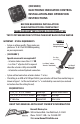

(EIC5000)
ELECTRONIC INDICATOR CONTROL
INSTALLATION AND OPERATION
INSTRUCTIONS
IMPORTANT - SPECIAL REQUIREMENTS:
System is voltage specic. Please make sure •
you have a 12 or 24 volt EIC5000 depending
on your requirements.
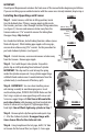
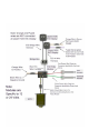
(SEE FIGURE 1)•
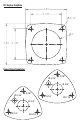
Special sensor coils are required if:
- Actuator stroke is more than 2 ½" OR
- Less than 1" of piston shaft is exposed
when the actuator is fully retracted OR
- Actuator has external hydraulic connection
System will not work when actuator stroke is 1" or less•
If installing in an M80 or M120 Sport Tab kit, your actuator will have three molded rings as •
shown in Figure 1. Cut the metal rod to 6 ⁄" as indicated by score mark (see enclosed
instruction sheet for cutting the rod).
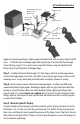
BEFORE BEGINNING INSTALLATION:
READ INSTRUCTIONS COMPLETELY
MAKE SURE BATTERY POWER IS DISCONNECTED
TEST SYSTEM BEFORE PUTTING THE BOAT BACK IN THE WATER
FIGURE 1
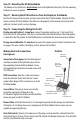
7/16", 1/2" & 9/16" Wrench Teon Tape Marine Grade Sealant
1/8", 3/16", 5/16" & 3/4" Drill Bit Wire Stripper Vise Grips
2" Hole Saw Electric Drill Wire Cutter
REQUIRED TOOLS
KEEP THIS MANUAL WITH BOAT OWNER’S INFORMATION
Bennett Marine, Inc.
550JimMoranBlvd•DeereldBeach,FL33442
Phone:954.427.1400•Fax:954.480.2897
Web: www.BennettTrimTabs.com
External Hydraulic
Tubing Connection
Three Rings
(cut rod only)
Less Than 1"
When Fully
Retracted
}
Less Than 1" or More
Than 2 ½" Total Stroke
}