Bennett SLT Owner’s Manual and Installation Instructions FOR SLT6 AND SLT10 KITS SLT10 SLT6 SAVE AND KEEP WITH BOAT OWNER’S INFORMATION
Congratulations on your purchase of a Bennett SLT System — an affordable, simple solution for small boats from 10 to 20 feet (3 m to 6 m). Now you have the durability of a Bennett trim tab system with a quick and easy installation.
Complete SLT Parts List and Diagram 1 2 3 4 SLT6 TPOSLT6 - Qty 2 HPSLT6 - Qty 2 BPSLT6 - Qty 2 A1200SSLT50 Qty 2 SLT500 - Qty 2 H1170SLT SLT10 TPOSLT10 - Qty 2 HPSLT10 - Qty 2 BPSLT10 - Qty 2 A1200SSLT80 Qty 2 SLT500 - Qty 2 H1170SLT H1174 - Qty 6 H1174 - Qty 6 7 Trim Tab Screw H1198 - Qty 10 H1198 - Qty 10 8 Mounting Bracket 9 Actuator Lower Hinge Screw SLT501 - Qty 2 H1175 - Qty 4 SLT501 - Qty 2 H1175 - Qty 4 Trim Tab Only Hinge Plate Backing Plate Complete Actuator 5 Actuator Pin Hardware Bag
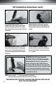
SLT Installation Instructions Standard RIB Installation 8" m " fro rive) ast 8 (At le erline of d cent Standard “V”Hull Installation 3"- 4" 8" Tools & Supplies Needed: from (At least 8"of drive) e in rl te n ce • Hand drill with 5/32" • Phillips screwdriver and 3/16" drill bits • Marine grade sealant • Tape measure • Straight edge Chine • Marking pencil • Glove Getting Started - Important Please Read 1. Checking for Obstructions.
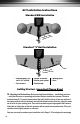
SLT Installation Instructions (cont.) 2. 3"- 4" Hole pattern closer to top edge 5/8" Chine st At learom drive 8" f terline of cen Position the Tab. Using the backing plate, choose a location 3-4" from the chine. Maintain a minimum of 8" from the centerline of your drive unit to the closest edge of the trim tab. Align the bottom of the backing plate flush with the bottom of the transom. The hole pattern on the backing plate should be closer to the top edge of the backing plate. 3.
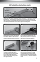
SLT Installation Instructions (cont.) 8. 7. Set Final Actuator Position. Use a straight edge under the trim tab to make sure the tab is flush with the hull bottom. This is important to ensure correct actuator placement. 9. Mark Actuator Position on Transom. Set the actuator upper hinge against the transom. Mark the three upper hinge hole centers. 10. Drill Actuator Holes. Use a 3/16" drill bit to drill the three holes.
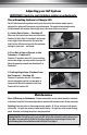
Adjusting your SLT System IMPORTANT: Conduct a sea trial before making any adjustments. Three Mounting Options to Change Lift: The SLT has three hole positions on the trim tab so that the actuator angle may be adjusted for optimum lift pressure and performance. The supplied mounting bracket installed under the actuator lower hinge covers the holes that are not used. 1.
bennett warranty Bennett SLT systems in the United States carry a five (5) year limited warranty against manufacturing defects. PLEASE NOTE: Damage to the trim tabs due to electrolysis is not covered by warranty. No labor costs of replacement, haulout, or miscellaneous charges are covered. Contacting Bennett Marine first may save considerable time, trouble and expense.