
User manual


21
integrated fuse (G fusible insert) 10 A (see gure 14). Proceed as follows to
replace the fuse:
- Disconnect the safety measuring lines from the measuring circuit.
- Disconnect the safety measuring lines from the BENNING MM 1-2/ 1-3.
- Switch the rotary switch 8 to position „OFF“.
- Put the BENNING MM 1-2/ 1-3 face down and unscrew the screw of the
battery compartment cover.
- Lift off the battery compartment cover from the bottom part.
- Remove the batteries from the battery compartment.
- Remove the suspension xture L (lift off the snap-on nose by means of a
small slotted screwdriver) from the bottom of the housing.
- Unscrew the four screws from the bottom of the housing.
Do not unscrew any screws from the printed circuit of the
BENNING MM 1‑2/ 1‑3!
- Lift off the bottom of the housing from the front part.
- Lift one end of the defective fuse out of the fuse holder.
- Completely remove the defective fuse from the fuse holder.
- Insert a new fuse of the same nominal current, of the same triggering
characteristics and of the same dimensions.
- Arrange the new fuse in the middle of the holder.
- Carefully place the bottom of the housing back onto the device. When
closing the bottom of the housing, make sure that the battery springs in the
bottom of the housing slide into the receptacle slots!
- Lock the bottom of the housing into place onto the front part and fasten the
four screws.
- Lock the suspension xture Linto place on the back of the bottom part of
the housing.
- Insert the batteries back into the battery compartment observing correct
polarity, close the battery compartment cover and tighten the screws.
See gure 14: Fuse replacement
9.5 Calibration
To maintain accuracy of the measuring results, the device must be recalibrated
in regular intervals by our factory service. We recommend recalibrating the
device once a year. For this purpose, send the device to the following address:
Benning Elektrotechnik & Elektronik GmbH & Co. KG
Service Center
Robert-Bosch-Str. 20
D - 46397 Bocholt
9.6 Spare parts
Fuse F 10 A, 600 V, 50 kA (Bussmann KTK or DCM) P.no. 748263
10. Usingthesuspensionxture
- You can store the safety measuring lines by winding them around the device
and by engaging the probe tips of the safety measuring lines in a protected
way on the suspension xture L (see gure 15).
- You can engage a safety measuring line on the suspension xture
L in such a way that the probe Tipp remains free in order to be able
to guide the probe tip towards a measuring point together with the
BENNING MM 1-1/ 1-2/ 1-3.
- The rear support of the device allows an inclined setup of the BENNING MM 1-
1/ 1-2/ 1-3 (facilitates reading the measured values) or suspension of the
device (see gure 16).
- The suspension xture L is equipped with a lug which can be used for
suspension.
See gure 15: Winding the safety measuring lines
See gure 16: Setting up the BENNING MM 1-1/ 1-2/ 1-3
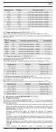
11. Technical data of the measuring accessories
4 mm safety measuring line ATL 2
- Standard: EN 61010-031,
- Maximum rated voltage to earth ( ) and measuring category:
1000 V CAT III, 600 V CAT IV,
- Maximum rated current: 10 A,
- Protection class II (
), continuous double or reinforced insulation,
- Contamination class: 2,
- Length: 1.4 m, AWG 18,
- Ambient conditions:
11/ 2007
BENNING MM 1‑1/ 1‑2/ 1‑3