D Bedienungsanleitung Operating manual Mehrsprachige Anleitung unter www.benning.
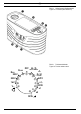
D Bild 1a: Gerätefrontseite/ Geräteoberseite Figure 1a: Front tester panel/ device top A 2 3 4 5 6 7 RISO 250 V RLOW D 500 V C OFF V A > 440 V 06/ 2018 Z S / ZI HIGH CURRENT E F G 1 kV B Bild 1b: Funktionswahlschalter Figure 1b: Function selector switch ZS / ZI H NO-TRIP I AUTO J x½ K RCDt x1 L M x5 RCDI BENNING IT 105
D N M L A Bild 1c: Displayanzeige Figure 1c: Digital display K B C J D E F G H I Bild 2: RLOW-/RISO-Messung Figure 2: RLOW-/RISO measurement schwarz black 06/ 2018 rot red BENNING IT 105
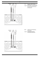
D Bild 3: schwarz black rot red Spannungsmessung über 4 mm Messleitungen Figure 3: Measurement of Voltage via of 4 mm measuring leads Bild 4: Spannungs-, RCD- und ZS-/ZI-Messung über Prüfkabel mit Schutzkontaktstecker Figure 4: Measurement of voltage, RCD and ZS (Zloop)/ZI (Zline) via test cable with shock-proof plug 06/ 2018 BENNING IT 105
D 06/ 2018 schwarz black grün green rot red Bild 5: schwarz black grün green rot red Bild 6: Spannungs-, RCD- und ZS-/ ZI-Messung über 4 mm Messleitung Figure 5: Measurement of voltage, RCD and ZS (Zloop)/ZI (Zline) via of 4 mm measuring leads ZI-Messung und PSC-Messung (Phase-Phase) Figure 6: ZI measurement and PSC measurement (phase-phase) BENNING IT 105
D schwarz black grün green rot red Bild 7: Drehfeldprüfung (Phasenfolge) Figure 7: Rotary field (phase sequence) Bild 8: Batterie-/ Sicherungswechsel Figure 8: Battery/fuse replacement Seriennummer serial number 06/ 2018 FF 1,6A 1000VDC BENNING IT 105
D Bedienungsanleitung BENNING IT 105 Das Installationsprüfgerät BENNING IT 105 ist ein multifunktionales Prüfgerät zur Prüfung elektrischer Anlagen gemäß DIN VDE 0100-600 (IEC 60364-6) und DIN VDE 0105-100 (EN 50110).
D > 440 V Warnung vor elektrischer Gefahr! Steht vor Hinweisen, die beachtet werden müssen, um Gefahren für Menschen zu vermeiden. Achtung Dokumentation beachten! Das Symbol gibt an, dass die Hinweise in der Bedienungsanleitung zu beachten sind, um Gefahren zu vermeiden. Das Prüfgerät nicht anwenden in Verteilersystemen mit Spannung höher als 440 V. Das Prüfgerät ist überhitzt.
D Die Messung des Schutzleiter- und Isolationswiderstandes darf nur an spannungslosen Anlageteilen durchgeführt werden. Messspitzen nicht berühren! Bei Isolationswiderstandsmessungen können hohe elektrische Spannungen an den Messspitzen anliegen. Während der Messung keine Metallteile des Prüfobjektes berühren. Das Prüfgerät BENNING IT 105 ist direkt nach beendeter Prüfung von der elektrischen Anlage zu trennen.
D - Das BENNING IT 105 benötigt sechs 1,5 V Mignon-Batterien/ Typ AA, IEC LR6 Hinweis auf optionales Zubehör: - 40 m Messleitung mit Aufwickler und Handschlaufe, zur Messung von Schutzleiterverbindungen (044039) 4.
D Hinweis: Sollte der Netzspannungsanzeiger blinken, überprüfen Sie den korrekten Anschluss der Messleitungen oder drehen Sie den Schutzkontaktstecker des Prüfkabels um 180°: - Rote Messleitung/-buchse L 5 mit Außenleiter L verbinden - Schwarze Messleitung/-buchse N 7 mit Neutralleiter N verbinden - Grüne Messleitung/-buchse PE 6 mit Erde PE verbinden Bei inkorrekter Netzspannung wird die Messung blockiert. M Warnsymbole.
D Prüfstrom: > 1 mA, < 2 mA bei Kurzschluss Anzahl der Wiederholungsprüfungen (DIN EN 61557-2): ca. 3000 Prüfspannungsanzeige: ± 5 % 7.4 Schleifenimpedanz (ZS) Messbereich Auflösung Messgenauigkeit hoher Prüfstrom: 0,20 Ω - 1999 Ω max.
D 8.1.1 Ein-, Ausschalten des BENNING IT 105 - Drehen Sie den Drehschalter 1 aus der Schaltstellung „OFF“ F in die gewünschte Messfunktion, um das BENNING IT 105 einzuschalten. - Das BENNING IT 105 schaltet sich nach ca. 5 Minuten selbstständig ab (APO, Auto-Power-Off). Es schaltet sich wieder ein, wenn der Drehschalter 1 aus der Schaltstellung „OFF“ eingeschaltet wird. 8.1.
D m Messleitungswiderstände können bis 10 Ohm kompensiert werden. AUTO-Start (F4): Bei aktiviertem AUTO-Start wird die Durchgangsprüfung automatisch gestartet, wenn der anliegende Widerstandswert an den Messspitzen < 20 kΩ beträgt. Die Funktion bleibt auch nach dem Ausschalten des Prüfgerätes gespeichert. - Messleitungen gemäß Bild 2 am BENNING IT 105 anschließen und mit dem Prüfobjekt kontaktieren.
D 8.5.1 Messung mit hohem Prüfstrom (HIGH CURRENT) m Eine Messung der Schleifenimpedanz ZS (L-PE) mit hohem Prüfstrom löst einen vorgeschalteten RCD-Schutzschalter aus! Sollte der RCD-Schutzschalter auslösen, wird in der Digitalanzeige 2 „RCD“ eingeblendet und die Messung wird unterbrochen. - Mit dem Drehschalter 1 die gewünschte Funktion ZS / ZI (HIGH CURRENT) G wählen. - In der Digitalanzeige 2 werden kurzzeitig die Symbole der Funktionstasten F1 A bis F4 D eingeblendet.
D 8.6 RCD-Prüfung Die Messung erfordert einen korrekten Anschluss der Netzspannung gemäß Bild 4, 5 oder 6 an das BENNING IT 105. Der Netzspannungsanzeiger muss dauerhaft leuchten: Sollte die Netzspannungsanzeige blinken, drehen Sie den Schutzkontaktstecker des Prüfkabels um 180° oder überprüfen Sie den korrekten Anschluss der Messleitungen.
D (F3): RECALL-Funktion, mit jeder Tastenbetätigung werden die Messwerte der letzten AUTO-Messung in der Digitalanzeige eingeblendet.
D Bei der Prüfung selektiver Fehlerstromschutzeinrichtungen startet die Messung nach einer Zeitverzögerung von 30 s. ► ► ► I∆N Nennfehlerstrom (F4): Über die Funktionstaste F4 können Sie den Nennfehlerstrom anwählen: Verfügbare Nennfehlerströme (sinusförmiger Prüfstrom) : ½ I∆N 1 I∆N 5 I∆N 10 mA 30 mA 100 mA 300 mA 500 mA - Messleitungen gemäß Bild 4 oder 5 am BENNING IT 105 anschließen und mit dem Prüfobjekt kontaktieren.
D - Das Hauptdisplay K zeigt den gemessenen Auslösestrom an. 9. Instandhaltung Vor dem Öffnen das BENNING IT 105 unbedingt spannungsfrei machen! Elektrische Gefahr! Die Arbeit am geöffneten BENNING IT 105 unter Spannung ist ausschließlich Elektrofachkräften vorbehalten, die dabei besondere Maßnahmen zur Unfallverhütung treffen müssen. So machen Sie das BENNING IT 105 spannungsfrei, bevor Sie das Gerät öffnen: - Schalten Sie das Prüfgerät aus - Trennen Sie alle Anschlussleitungen vom Gerät 9.
D - Legen Sie das BENNING IT 105 auf die Frontseite und lösen Sie die Schrauben vom Batteriedeckel. - Heben Sie den Batteriedeckel vom Unterteil ab. - Heben Sie ein Ende der defekten Sicherung seitlich mit einem Schlitzschraubendreher aus dem Sicherungshalter. - Entnehmen Sie die defekte Sicherung vollständig aus dem Sicherungshalter. - Setzen Sie die neue Sicherung ein.
Operating manual BENNING IT 105 The BENNING IT 105 installation tester is a multifunctional tester for testing electrical installations in compliance with IEC 60364-6 (DIN VDE 0100-600) and EN 50110 (DIN VDE 0105-100).
> 440 V Warning of electrical danger! Indicates instructions which must be followed to avoid danger to persons. Important, comply with the documentation! This symbol indicates that the stipulations in the operating instructions must be followed in order to avoid danger. Do not use the tester in distribution systems with voltages higher than 440 V. The tester is overheated.
Measurements of the protective conductor resistance and of the insulating resistance must be carried out at idle system parts only. Do not touch the measuring probes! During insulating resistance measurements, high electric currents might be applied to the measuring probes. Do not touch any metal parts of the test object during measurement. Disconnect the BENNING IT 105 from the electrical system directly after the test is finished.
Note on optional accessories: - 40 m measuring lead with rewinder and wrist strap, for measuring protective conductor connections (044039). 4.
- Connect the red measuring lead/jack L 5 to the external conductor L. - Connect the black measuring lead/jack N 7 to the neutral conductor N. - Connect the green measuring lead/jack PE 6 to earth PE. In case of an incorrect mains voltage, measurement will be blocked. M Warning symbols. “Warning of electrical danger!”, “Attention! Please observe documentation!” and “Tester is overheated!”; please observe the relevant sections of this operating manual. N Symbol indicating a defective fuse 5.
7.4 Loop impedance (ZS) Measuring range Resolution Accuracy high test current: 0.20 Ω - 1999 Ω max. 0.01 Ω ± (5 % + 5 digits) without RCD tripping: 1.00 Ω - 1.99 Ω 0.01 Ω ± (5 % + 12 digits) 2.0 Ω - 19.9 Ω 0.
- The BENNING IT 105 switches off automatically after approx. 5 minutes (APO, Auto-Power-Off). It switches on again, if the rotary switch 1 is switched on from switch position “OFF”. 8.1.2 Testing the battery condition During switch-on and operation, the BENNING IT 105 performs an automatic battery test. Discharged batteries are indicated by a battery symbol I on the LC display 2. As soon as the battery symbol I flashes, the batteries have to be replaced by new ones immediately (see section 9.
tance value applied to the measuring probes is < 20 kΩ. The function remains stored even after switching off the tester. - Connect the measuring leads to the BENNING IT 105 as shown in figure 2 and apply them to the test object. - The continuity test is started automatically if the AUTO start function has been enabled via the function key F4 3. Alternatively, press and hold the TEST key 4 to start the continuity test.
8.5.1 Measurement with high test current (HIGH CURRENT) m Measuring the loop impedance ZS (L-PE) with a high testing current will trigger an upstream RCD! If the RCD trips, “RCD” is indicated on the digital display 2 and measurement will be interrupted. - Select the desired function ZS/ZI (HIGH CURRENT) G with the rotary switch 1. - The symbols of the function keys F1 A to F4 D are briefly shown on the digital display 2.
8.6 RCD test Measurement requires correct connection of the mains voltage to the BENNING IT 105 as shown in figures 4, 5 or 6. The mains voltage indicator must light permanently: If the mains voltage indicator flashes, turn the shock-proof plug of the test cable by 180° or check the measuring leads for correct connection.
(F3): RECALL function; the measured values of the last AUTO measurement are shown on the digital display each time a key is pressed.
► ► ► I∆N nominal fault current (F4): Press the function key F4 to select the nominal fault current: Available nominal fault currents (sinusoidal testing current) : ½ I∆N 1 I∆N 5 I∆N 10 mA 30 mA 100 mA 300 mA 500 mA - Connect the measuring leads to the BENNING IT 105 as shown in figures 4 or 5 and apply them to the test object. - Press the TEST key 4 to start the measurement. - The measured tripping time is shown on the main display K. 8.6.
9. Maintenance Before opening the BENNING IT 105, ensure that it is not connected to a source of voltage! Electrical danger! Any work required on the BENNING IT 105 when it is under voltage must be done only by a qualified electrician. Special steps must be taken to prevent accidents. Before opening the BENNING IT 105, remove it from all sources of voltage as follows - Turn the rotating switch 1 to ”OFF”. - Disconnect all connecting cables from the device. 9.
- Push the defective fuse out of the fuse holder completely. - Insert a new fuse which has the same rated current, same rated voltage, same breaking capacity, same triggering characteristics and same dimensions. - Lock the battery compartment cover into place on the bottom part and tighten the screws. See figure 8: Fuse replacement 9.5 Calibration Benning guarantees compliance with the technical and accuracy specifications stated in the operating manual for the first 12 months after the delivery date.
Benning Elektrotechnik & Elektronik GmbH & Co. KG Münsterstraße 135 - 137 D - 46397 Bocholt Phone: +49 (0) 2871 - 93 - 0 • Fax: +49 (0) 2871 - 93 - 429 www.benning.de • E-Mail: duspol@benning.