
Instructions
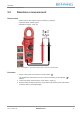
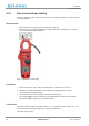

Table Of Contents
- Legal notice
- Table of contents
- Table of figures
- List of tables
- 1 Introduction
- 2 Safety
- 3 Scope of delivery
- 4 Device description
- 5 Operation
- 6 Maintenance
- 7 Technical data
- 8 Disposal and environmental protection
- Index

Operation
5.9 Voltage indicator
5191 / 07/2021 en BENNING CM 2-1 35
5.9.2 External conductor or phase testing
Requirements
• Please observe the requirements for measuring [}page26].
• Approved red safety measuring line
• Make sure that no voltage is applied to the COMjack of the device. Remove a connected
black safety measuring line.
Procedure
1. Set the rotary switch of the device to switch position “Volt Sense/ Lo‑Z Auto‑V”.
2. Connect the red safety measuring line to the “+”jack of the device [}page27].
3. Press the “ACHFR/ DCAZERO” key to enable the “Voltage indicator” function.
“EF” is shown on the digital display.
4. Bring the safety measuring lines into contact with the measuring point (system part).
If the symbols “ ” and “EF” are flashing on the digital display, the phase of an earthed
alternating voltage is applied to this measuring point.