D Bedienungsanleitung Operating manual ST 710 R PE R ISO M BENNING ST 710 mA ON/OFF press 2 sec.
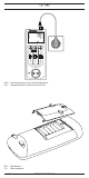
D ST ST 710 710 R PE R PE R ISO R ISO 5 M M mA mA 2 4 ON/OFF ON/OFF press 2 sec. 3 press 2 sec.
D ST 710 R PE R ISO M mA ON/OFF press 2 sec. Klasse I Class I Klasse II Class II RPE Leitung Cord RPE RISO RISO RISO IEA IEA Leitungstest Wiring DIN VDE 0701/0702, BGV A3, ÖVE/ÖNORM E 8701, NEN 3140 Prüfling während der Prüfung einschalten Switch on test object during test Bild 3: Prüfung von Geräten der Schutzklasse I (Geräte mit Schutzleiter und berührbaren leitfähigen Teilen die am Schutzleiter angeschlossen sind) Fig.
D ST 710 R PE R ISO M mA ON/OFF press 2 sec. Klasse I Klasse II Class I Leitung Class II Cord RPE RPE RISO RISO RISO IEA IEA Leitungstest Wiring DIN VDE 0701/0702, BGV A3, ÖVE/ÖNORM E 8701, NEN 3140 Prüfling während der Prüfung einschalten Switch on test object during test Bild 5a: Prüfung von Geräteanschlussleitungen mit Kaltgerätestecker Fig. 5a: Testing of device connecting cables with IEC connector ST 710 R PE R ISO M mA ON/OFF press 2 sec.
D ST 710 LN LE NE V V ON/OFF press 2 sec. Klasse I Class I Klasse II Class II RPE Leitung Cord RPE RISO RISO RISO IEA IEA Leitungstest Wiring DIN VDE 0701/0702, BGV A3, ÖVE/ÖNORM E 8701, NEN 3140 Prüfling während der Prüfung einschalten Switch on test object during test Bild 6: Fig. 6: Spannungsmessung an externer Schutzkontaktsteckdose Voltage measurement on external shock-proof socket Bild 7: Fig.
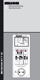
D Bedienungsanleitung BENNING ST 710 Gerätetester zur sicherheitstechnischen Prüfung ortsveränderlicher elektrischer Geräte/ Betriebsmittel Prüfung gemäß DIN VDE 701/ 0702, ÖVE/ ÖNORM E 8701 Prüfung von Leitungsrollern, Mehrfachverteilern und Kaltgeräteleitungen Spannungsmessung an externer Schutzkontaktsteckdose Inhaltsverzeichnis 1. Benutzerhinweise 2. Sicherheitshinweise 3. Lieferumfang 4. Gerätebeschreibung 5. Allgemeine Angaben 6. Umgebungsbedingungen 7. Elektrische Angaben 8.
D 2. Sicherheitshinweise Das Gerät ist gemäß DIN VDE 0404 Teil 1 und 2 DIN VDE 0411 Teil 1/ EN 61010 Teil 1 DIN VDE 0413 Teil 1/ EN 61557 Teil 1, 2, 4 und 10 gebaut und geprüft und hat das Werk in einem sicherheitstechnisch einwandfreien Zustand verlassen. Um diesen Zustand zu erhalten und einen gefahrlosen Betrieb sicherzustellen, muss der Anwender die Hinweise und Warnvermerke beachten, die in dieser Anleitung enthalten sind.
D - 16 A CEE-Kupplung – CEE-Stecker (044127) 32 A CEE-Kupplung – CEE-Stecker (044128) Prüfprotkoll-Formulare “Prüfung elektrischer Geräte” können Sie kostenlos unter www.benning.de downloaden 4.
D 7.3 Schutzleiter- und Berührungsstrom über Ersatzableitstromverfahren Messbereich Auflösung 0,10 mA - 20 mA 0,01 mA Messgenauigkeit 5 % ± 2 Digit Prüfspannung: 40 VAC, 50 Hz Prüfstrom: < 5 mA bei 2 kΩ 7.4 Leitungstest - Messung des Schutzleiterwiderstandes gemäß 7.1 - Messung des Isolationswiderstandes gemäß 7.2 - Leitungsbruchprüfung von Außenleiter (L) und Neutralleiter (N) - Kurzschlussprüfung von Außenleiter (L) und Neutralleiter (N) 7.
D Vor Prüfbeginn ist das Prüfobjekt einzuschalten. (Netzschalter ein) Zur Beginn der Prüfung ist zu prüfen, ob der gewählte Prüfablauf zur Schutzklasse des angeschlossenen Prüfobjektes stimmt. 8.1.1 Ein-, Ausschalten des BENNING ST 710 Durch ein gedrückt halten der Tasten 2 + 3 für ca. 3 Sekunden wird das BENNING ST 710 eingeschaltet, 2 Signaltöne bestätigen dies. Erneutes drücken der Tasten schaltet das Gerät aus. Das BENNING ST 710 schaltet sich nach ca. 3 Minuten selbstständig ab.
D - Falls RPE kleiner als der zulässige Grenzwert ist, wird der Messwert von RPE angezeigt und ein erscheint neben dem RPE-Symbol. Die Messung von RPE wird nun wiederholt mit vertauschter Polarität durchgeführt. Nach bestandener Prüfung von RPE wird die Prüfung des Isolationswiderstandes gestartet. - Sollte im Display „Lo LOAD“ erscheinen, überprüfen Sie, ob das Prüfobjekt eingeschaltet ist. - Durch drücken der Taste 2 wird bei zu geringer Last (RL-N < 100 kΩ) der Prüfablauf fortgesetzt.
D 8.2.2 Prüfung von Geräten der Schutzklasse II (Schutzisoliert) und von Geräten der Schutzklasse III (Schutzkleinspannung) Prüfung von Geräten ohne Schutzleiter und mit berührbaren leitfähigen Teilen. Das Prüfobjekt muss an die Prüfsteckdose 1 des BENNING ST 710 angeschlossen werden. Stellen Sie eine Verbindung zwischen der 4 mm Prüfbuchse 6 und einem Metallteil des Prüfobjekts mittels der Prüfleitung mit Abgreifklemme her. Schalten Sie das Prüfobjekt ein.
D Querschnitt Länge 1,0 mm² 1.5 mm² 2,5 mm² 5m 0,1 Ω 0,06 Ω 0,04 Ω 10 m 0,2 Ω 0,12 Ω 0,08 Ω 25 m 0,5 Ω 0,3 Ω 0,2 Ω 50 m 1,0 Ω 0,6 Ω 0,4 Ω Tabelle 1: - - Widerstandwerte des Schutzleiters in Abhängigkeit von Länge und Querschnitt Nach bestandener Prüfung von RPE wird automatisch die Isolationswiderstandsmessung durchgeführt. Je nach Grenzwertüber- oder -unterschreitung wird ein oder ein neben dem RISOSymbol angezeigt.
D oder siehe Bild 9. Es werden nur die Spannungspotentiale zwischen den einzelnen Anschlüssen L, N und PE gemessen. Die Messung gibt keine Aussage über die fachgerechte Installation der Schutzkontaktsteckdose.
D 9.4 Kalibrierung Um die angegebenen Genauigkeiten der Messergebnisse zu erhalten, muss das Gerät regelmäßig durch unseren Werksservice kalibriert werden. Wir empfehlen ein Kalibrierintervall von einem Jahr. Senden Sie hierzu das Gerät an folgende Adresse: Benning Elektrotechnik & Elektronik GmbH & Co. KG Service Center Robert-Bosch-Str. 20 D – 46397 Bocholt 10. Umweltschutz Bitte führen Sie das Gerät am Ende seiner Lebensdauer den zur Verfügung stehen den Rückgabe- und Sammelsystemen zu.
Operating instructions BENNING ST 710 Appliance tester for safety-related testing of portable electrical devices and equipment testing according to DIN VDE 701/ 0702, ÖVE/ ÖNORM E 8701 testing of cable reels, multiple distributors and IEC power cords voltage measurement on external shock-proof socket Table of contents 1. User notes 2. Safety note 3. Scope of delivery 4. Unit description 5. General information 6. Environment conditions: 7. Electrical specifications 8.
2. Safety note The instrument is built and tested in accordance with DIN VDE 0404 part 1 and 2 DIN VDE 0411 part 1/ EN 61010 part 1 DIN VDE 0413 part 1/ EN 61557 part 1, 2, 4 and 10 and has left the factory in perfectly safe technical state. To maintain this state and ensure safe operation of the appliance tester, the user must observe the notes and warnings given in these instructions at all times. Improper handling and nonobservance of the warnings might involve severe injuries or danger to life.
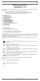
- 32 A CEE coupling - CEE plug (044128) Test certificate forms for "Testing of electrical devices" are available for download free of charge at www.benning.de 4. Unit description See figure 1: Appliance front face See figure 2: Top side of the device The display and operator control elements specified in Fig.
7.3 Protective conductor current and contact current by means of alternative leakage current measurement method Measuring range Resolution 0.10 mA - 20 mA 0.01 mA Measuring accuracy 5 % ± 2 Digit Testing voltage: 40 VAC, 50 Hz Testing current: < 5 mA at 2 kΩ 7.4 Cord test - measurement of the protective conductor resistance according to 7.1 - measurement of the insulating resistance according to 7.
At the beginning of the test it has to be checked whether the selected testing procedure complies with the protection class of the connected test object. 8.1.1 Switching the BENNING ST 710 ON/ OFF Press and hold the keys 2 and 3 for approx. 3 seconds to switch the BENNING ST 710 on. 2 acoustic signals confirm that the device is switched on. Press the keys again to switch the device off. After approx. 3 minutes, the BENNING ST 710 switches off automatically (APO, Auto PowerOff).
- If RPE is lower than the admissible limiting value, the measured value of RPE is shown and a appears next to the RPE symbol. Now, the RPE measurement is carried out again with reversed polarity. After the RPE test has been passed, the test of the insulating resistance is started. - If "Lo LOAD" is shown on the display, please check whether the test object is switched on. - Press the key 2 to continue the testing procedure in case of the load being too low (RL-N < 100 kΩ).
8.2.2 Testing of devices of protection class II (shock-proof) and of devices of protection class III (safety extra-low voltage) Testing of devices without protective conductor and with accessible conductive parts Connect the test object to the test socket 1 of the BENNING ST 710. Establish a connection between the 4 mm test socket 6 and a metal part of the test object by means of the test cable with alligator clip. Switch the test object on. Press the key 3 to start the automatic testing procedure.
Cross-section Length 1.0 mm² 1.5 mm² 2.5 mm² 5m 0.1 Ω 0.06 Ω 0.04 Ω 10 m 0.2 Ω 0.12 Ω 0.08 Ω 25 m 0.5 Ω 0.3 Ω 0.2 Ω 50 m 1.0 Ω 0.6 Ω 0.4 Ω Table 1: Resistance values of the protective conductor depending on length and cross-section - After the RPE test has been passed, the measurement of the insulating resistance is carried out automatically. Depending on whether the value is higher or lower than the limiting value, a or a is indicated next to the RISO symbol.
or Only the voltage potentials between the individual connections L, N and PE are measured. The measurement does not provide any information on the proper installation of the shock-proof socket. There will be no warning in case of a dangerous contact voltage of the PE conductor! See figure 6: 9.
9.4 Calibration To maintain the specified precision of the measurement results, the instrument must be recalibrated at regular intervals by our factory service. We recommend a recalibration interval of one year. Send the appliance to the following address: BENNING Elektrotechnik & Elektronik GmbH & Co. KG Service Centre Robert-Bosch-Str. 20 D - 46397 Bocholt 10. Environmental notice At the end of the product’s useful life, please dispose of it at appropriate collection points provided in your country.
Benning Elektrotechnik & Elektronik GmbH & Co. KG Münsterstraße 135 - 137 D - 46397 Bocholt Phone: +49 (0) 2871 - 93 - 0 • Fax: +49 (0) 2871 - 93 - 429 www.benning.de • E-Mail: duspol@benning.