D F Bedienungsanleitung Operating manual Notice d’emploi Gebruiksaanwijzing ST 725 LN LE NE R PE V k R ISO 2500V M ms mA ms mA 180° LEAK 0° B BENNING ST 725 (050316) STORE RECALL ON/OFF press 2 sec.
D Bedienungsanleitung Operating manual Mehrsprachige Anleitung auf beigefügter CD und unter www.benning.de Multilingual manuals on included CD and at D Anleitung des BENNING ST 725 mit Schweizer Steckersystem und Firmware (Art.-Nr. 050317) auf beigefügter CD oder unter www.benning.de Manual of BENNING ST 725 with Swiss plug system and firmware (item no.
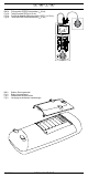
DF 9 L J K ST 725 R PE R ISO M mA LEAK 8 ON/OFF press 2 sec. 2 IPE IB 3 4 5 250 V 500 V 30 mA RCD 3 Phase 7 6 DIN VDE 0701-0702, DGUV V3, ÖVE / ÖNORM E 8701, NEN 3140 Prüfling während der Prüfung einschalten Switch on test object during test Bild 1: Fig. 1: Fig. 1: Fig. 1: Gerätefrontseite Appliance front face Partie avant de l’appareil Voorzijde van het apparaat J 9 L Bild 2: Fig. 2: Fig. 2: Fig.
DF Bild 3: Fig. 3: Fig. 3: Fig. 3: Spannungsmessung an externer Schutzkontaktsteckdose Voltage measurement on external shock-proof socket Mesure de tension sur une prise de courant de sécurité externe Spanningsmeting aan externe veiligheidswandcontactdoos ST 725 LN LE NE R PE V k R ISO 2500V V M ms mA ms mA 180° LEAK 0° B STORE RECALL ON/OFF press 2 sec.
DF Bild 5: Prüfung von Geräten der Schutzklasse II (Schutzisolierte Geräte ohne Schutzleiter und mit berührbaren leitfähigen Teilen) bzw. Prüfung von Geräten der Schutzklasse III (Schutzkleinspannung) Fig. 5: Testing of devices of protection class II (shock-proof devices without protective conductor and with accessible conductive parts) and testing of devices of protection class III (safety extra-low voltage) Fig.
DF Bild 6b: Fig. 6b: Fig. 6b: Fig. 6b: Prüfung von Leitungen, Mehrfachverteilern und Leitungsroller Testing of lines, multiple distributors and cable reels Contrôle de câbles, de câbles de distribution multiple et d'enrouleurs de câble Testen van kabels, verdeeldozen en kabelhaspels ST 725 LN LE NE R PE V k R ISO 2500V M ms mA ms mA 180° LEAK 0° B STORE RECALL ON/OFF press 2 sec.
DF Bild 7b: Fig. 7b: Fig. 7b: Fig.
DF Bild 8b: Fig. 8b: Fig. 8b: Fig. 8b: Prüfung mobiler FI/PRCD Schutzschalter (IΔN 30 mA) Testing of portable PRCDs (IΔN 30 mA) Contrôle de dispositifs différentiels portatifs « PRCD » (IΔN 30 mA) Test mobiele PRCD-beschermschakelaar (IΔN 30 mA) ST 725 LN LE NE R PE V k R ISO 2500V M ms mA ms mA 180° LEAK 0° B STORE RECALL ON/OFF press 2 sec.
DF Bild 10.
D Bedienungsanleitung BENNING ST 725 Gerätetester zur sicherheitstechnischen Prüfung ortsveränderlicher elektrischer Geräte/Betriebsmittel Prüfung elektrischer Geräte gemäß DIN VDE 0701-0702, DGUV Vorschrift 3, ÖVE/ ÖNORM E 8701, NEN 3140 Prüfung von Leitungsrollern, Mehrfachverteilern und Kaltgeräteleitungen Prüfung 3-phasiger elektrischer Geräte über optionale Messadapter Auslösezeitmessung von fest installierten FI/RCD- und mobilen FI/PRCD-Schutzschaltern Spannungsmessung an externer Schutzkontaktsteckdo
D In der Bedienungsanleitung und auf dem BENNING ST 725 werden folgende Symbole verwendet: Warnung vor elektrischer Gefahr! Steht vor Hinweisen, die beachtet werden müssen, um Gefahren für Menschen zu vermeiden. Achtung Dokumentation beachten! Das Symbol gibt an, dass die Hinweise in der Bedienungsanleitung zu beachten sind, um Gefahren zu vermeiden. Dieses Symbol auf dem BENNING ST 725 bedeutet, dass das BENNING ST 725 konform zu den EU-Richtlinien ist.
D Vor jeder Inbetriebnahme überprüfen Sie das Gerät und die Leitungen auf Beschädigungen. Ist anzunehmen, dass ein gefahrloser Betrieb nicht mehr möglich ist, ist das Gerät außer Betrieb zu setzen und gegen unbeabsichtigten Betrieb zu sichern.
D isoliert: 16 A Schutzkontaktkupplung - 16 A Schutzkontaktstecker (044131) 16 A CEE-Kupplung 5-polig - 16 A CEE-Stecker 5-polig (044127) 32 A CEE-Kupplung 5-polig - 32 A CEE-Stecker 5-polig (044128) - Prüfprotokoll-Formulare “Prüfung elektrischer Geräte” können Sie kostenlos downloaden unter www.benning.de siehe Bild 10: Optionales Zubehör 4.
D einer Anzahl von Digit (d.h. Zahlenschritte der letzten Stelle). Diese Messgenauigkeit gilt bei Temperaturen von 18 °C bis 28 °C und einer relativen Luftfeuchtigkeit kleiner 80 %. 7.1 Schutzleiterwiderstand Messbereich Auflösung 0,05 Ω - 19,99 Ω 0,01 Ω Messgenauigkeit 5 % ± 2 Digit Prüfstrom: > 200 mA (2 Ω) Leerlaufspannung: 4V-9V Voreingestellter Grenzwert: 0,3 Ω 7.
D Voreingestellter Grenzwert: 0,5 mA (SK II) Fremdspannungsfestigkeit: max. 276 V Bei nicht-sinusförmiger Stromversorgung ist ein zusätzlicher Fehler zu berücksichtigen: Crest-Factor von >1,4 bis 2,0, zusätzlicher Fehler + 3,1 % 7.6 - Leitungstest Messung des Schutzleiterwiderstandes gemäß 7.1 Messung des Isolationswiderstandes gemäß 7.2 Leitungsbruchprüfung von Außenleiter (L) und Neutralleiter (N) Kurzschlussprüfung von Außenleiter (L) und Neutralleiter (N) 7.
D Berührungsstrom IEA/ ILEAK ≤ 0,5 mA an leitfähigen Teilen ohne PE-Verbindung ≤ 0,5 mA an leitfähigen Teilen ohne PE-Verbindung 8. Prüfen mit dem BENNING ST 725 8.1 Vorbereiten der Prüfung Benutzen und lagern Sie das BENNING ST 725 nur bei den angegebenen Lager- und Arbeitstemperaturbedingungen, vermeiden Sie dauernde Sonneneinstrahlung. Angaben von Nennspannung und Nennstrom auf den Sicherheitsmessleitungen überprüfen.
D oder - Falls die Spannungspotentiale innerhalb nachfolgender Grenzwerte liegen, erscheint ein neben den LN-, LE- und NE-Symbolen. LN 195 V - 253 V LE 195 V - 253 V NE < 30 V LN oder 195 V - 253 V LE < 30 V NE 195 V - 253 V Es werden nur die Spannungspotentiale zwischen den einzelnen Anschlüssen L, N und PE gemessen. Die Messung gibt keine Aussage über die fachgerechte Installation der Schutzkontaktsteckdose.
D - Schalten Sie das Prüfobjekt ein. Durch drücken der -Taste 2 startet der automatische Prüfablauf. Die Prüfung beginnt mit der Messung des Schutzleiterwiderstandes RPE. Falls RPE größer als 1 Ω ist, wird der Messwert von RPE im Display angezeigt und ein erscheint neben dem RPE-Symbol. Der Abbruch wird durch den Hinweis „FAIL“ im Display bestätigt.
D BENNING ST 725 im Netzbetrieb: Das BENNING ST 725 unterbricht den Prüfablauf nach der RISO-Messung und fordert den Anwender durch eine blinkende Anzeige „ILEAK“ auf, die 230 V Netzspannung auf die Prüfsteckdose 1 zu schalten. Vergewissern Sie sich, dass der Prüfling gesichert ist und drücken Sie die -Taste 4, um den Schutzleiterstrom im Differenzstromverfahren zu messen. Die Messung des Schutzleiterstromes (Differenzstromverfahren) startet nur bei korrekt anliegender Netzspannung.
D messungen mit hohem Laststrom durchzuführen. Sollte die zulässige interne Betriebstemperatur überschritten werden, wird das Symbol „StOP“ und „hot“ im Display eingeblendet. In diesem Fall ist das BENNING ST 725 vom Netz zu trennen und kann nach einer ausreichenden Abkühlphase erneut eingesetzt werden. Hinweis zur Messung des Berührungsstromes: Berührbare leitfähige Teile, die nicht mit dem Schutzleiter verbunden sind, sind gemäß Abschnitt 9.2 zu prüfen.
D Schritt 1 von 2: - ach einer Messzeit von 5 Sekunden oder durch eine erneute Betätigung der Taste 4 wird N das Netz umgepolt und der Berührungsstrom wird mit umgepolter Netzspannung („L/N“ – „N/L") gemessen. Der höchste Messwert beider Messungen wird angezeigt. Schritt 2 von 2: - Falls der Berührungsstrom kleiner als der zulässige Grenzwert ist, erscheint ein neben dem ILEAK-Symbol. Die Gesamtprüfung gilt als bestanden, wenn das Symbol „PASS“ im Display erscheint.
D 9.3 Leitungstest Der Leitungstest kann zur Prüfung von Kaltgeräteleitungen (Geräteanschlussleitungen mit Kaltgerätekupplung) als auch zur Prüfung von Leitungsroller, Mehrfachverteilern und Verlängerungsleitungen genutzt werden. 9.3.1 Prüfung von Kaltgeräteleitungen (IEC-Adapterleitungen) Entfernen Sie den Stecker der Netzanschlussleitung aus Buchse K des BENNING ST 725. Schließen Sie die zu prüfende Kaltgeräteleitung über den Kaltgerätestecker J an das BENNING ST 725 an.
D Bestätigt den Leitungsbruch von Außenleiter (L) oder Neutralleiter (N) Symbol „Shor“: Bestätigt den Kurzschluss zwischen Außenleiter (L) und Neutralleiter (N) siehe Bild 6a: Prüfung von Geräteanschlussleitungen mit Kaltgerätestecker - Hinweis zur Messung des Schutzleiterwiderstandes: Die Messung des Schutzleiterwiderstandes RPE kann alternativ auch als Dauermessung (max. 2 x 90 Sek.) durchgeführt werden. Drücken Sie hierzu die Taste 2 für ca. > 5 Sekunden bis das Symbol im Display erscheint.
D - - - Andernfalls startet die Messung des Schutzleiterwiderstandes RPE mit automatischer Polaritätsumkehr und der höchste Messwert beider Messungen wird im Display eingeblendet. Nach bestandener Prüfung von RPE erfolgt die Messung des Schutzleiterstromes ILEAK als Dauermessung für max. 30 Sekunden. Durch drücken der -Taste 7 kann die Messung vorzeitig beendet werden. Falls der Schutzleiterstrom kleiner als der zulässige Grenzwert ist, erscheint ein neben dem ILEAK-Symbol.
D Vor der Prüfung eines FI/RCD-Schutzschalters ist der 4 mm Sicherheitsstecker der Prüfleitung aus der Prüfsteckdose 9 zu entfernen. Die Messung kann beeinflusst werden durch: - Eine eventuell vorhandene Spannung zwischen Schutzleiter der Schutzkontaktsteckdose und Erde Ableitströme im Stromkreis hinter dem FI/RCD-Schutzschalter Weitere Erdungseinrichtungen - Betriebsmittel, die hinter dem FI/RCD-Schutzschalter angeschlossen sind und eine Verlängerung der Auslösezeit verursachen, z.B.
D oder - - - Stecken Sie den mobilen FI/PRCD-Schutzschalter in die Prüfsteckdose 1 des BENNING ST 725. Schließen Sie die im Lieferumfang befindliche Kaltgeräteleitung an den Kaltgerätestecker J des BENNING ST 725 an und stecken Sie den Schutzkontaktstecker wie in Bild 8b dargestellt in den mobilen FI/PRCD-Schutzschalter. Der Kabelaustritt muss Richtung Display zeigen! Durch drücken der -Taste 6 wird die Netzspannung auf die Prüfsteckdose 1 geschaltet. Im Display erscheint „rCd“ und „rESEt“.
D 10.2 Messwerte aufrufen Drücken Sie die -Taste , um die gespeicherten Messwerte mit der zugehörigen Spei cherplatznummer wieder aufzurufen. Das Symbol "RECALL" erscheint im Display 8. Durch erneutes Drücken der -Taste wird zum nächsten Speicherplatz gewechselt. Durch Drücken der -Taste kann zum vorherigen Speicherplatz gewechselt werden. 10.3 Messwertspeicher löschen Drücken Sie die -Taste , um die gespeicherten Messwerte mit der zugehörigen Spei cherplatznummer wieder aufzurufen.
D 10.6 Einstellen von Datum und Uhrzeit Das BENNING ST 725 besitzt eine integrierte Echtzeituhr, um jeden Speichervorgang ein Datum-Zeitstempel hinzuzufügen. Für die Einstellung von Datum und Uhrzeit führen Sie folgende Schritte aus: Schalten Sie das BENNING ST 725 durch gleichzeitiges Betätigen der -Taste 2 und -Taste 3 aus. Drücken und halten Sie die -Taste und betätigen Sie gleichzeitig die -Taste 2 und -Taste 3. Das Datum-/Uhrzeitformat wird wie folgt angezeigt: MM.DD = Monat (1-12).
D 11.4 Sicherungswechsel Vor dem Öffnen das BENNING ST 725 unbedingt spannungsfrei machen! Elektrische Gefahr! Das BENNING ST 725 wird durch zwei eingebaute Sicherungen (16 A, 250 V, F, D = 5 mm, L = 20 mm), (10019440) vor Überlastung geschützt. So wechseln Sie die Sicherungen (siehe Bild 9): Schalten Sie das BENNING ST 725 aus. Legen Sie das BENNING ST 725 auf die Frontseite und lösen Sie die Schraube vom Batteriedeckel.
Operating instructions BENNING ST 725 Appliance tester for safety-related testing of portable electrical devices and equipment testing of electrical appliances according to DIN VDE 0701-0702, DGUV Regulation 3, NEN 3140 testing of cable reels, multiple distributors and IEC power cords testing of three-phase electrical appliances by means of optional measuring adapters tripping time measurement of permanently installed RCDs and portable RCDs (PRCDs) voltage measurement on external shock-proof socket Table
in Section 6. “Ambient conditions”). The following symbols are used in these operating instructions and on the BENNING ST 725: Warning of electrical danger! Indicates instructions which must be followed to avoid danger to persons. Important, comply with the documentation! The symbol indicates that the information provided in the operating instructions must be complied with in order to avoid risks. This symbol on the BENNING ST 725 means that the BENNING ST 725 complies with the EU directives.
Should it appear that safe operation of the appliance tester is no longer possible, it should be shut down immediately and secured to prevent it being switched on accidentally. It may be assumed that safe operation is no longer possible: if the instrument show visible signs of damage if the appliance tester no longer functions after long periods of storage under unfavourable conditions after being subjected to rough transport the device is exposed to moisture.
32 A CEE coupling (5-pin) - CEE plug (5-pin) (044128) Test certificate forms for "Testing of electrical devices" are available for download free of charge at www.benning.de See figure 10: Optional accessories - 4. Unit description See figure 1: Appliance front face See figure 2: Top side of the device The display and operator control elements specified in Fig.
7.1 Protective conductor resistance Measuring range Resolution 0.05 Ω - 19.99 Ω 0.01 Ω Measuring accuracy 5 % ± 2 digits Testing current: > 200 mA (2 Ω) Open-circuit voltage: 4V-9V Preset limiting value: 0.3 Ω 7.2 Insulating resistance Measuring range Resolution Measuring accuracy 0.1 MΩ - 19.99 MΩ 0.
Resistance to external voltages: max. 276 V For non-sinusoidal current supply, an additional error has to be considered: crest factor of > 1.4 to 2.0, additional error + 3.1 % 7.6 - Cord test measurement of the protective conductor resistance according to 7.1 measurement of the insulating resistance according to 7.2 line break testing of the external conductor (L) and the neutral conductor (N) short-circuit testing of the external conductor (L) and the neutral conductor (N) 7.
8. Measuring with the BENNING ST 725 8.1 Preparations for measuring Operate and store the BENNING ST 725 only at the specified storage and operating temperatures conditions. Do not permanently expose the device to sunlight. Check rated voltage and rated current details specified on the safety measuring leads. Strong sources of interference in the vicinity of the BENNING ST 725 might lead to unstable readings and measuring errors.
LN 195 V - 253 V LE 195 V - 253 V NE < 30 V LN or 195 V - 253 V LE < 30 V NE 195 V - 253 V Only the voltage potentials between the individual connections L, N and PE are measured. The measurement does not provide any information on the proper installation of the shock-proof socket. There will be no warning in case of a dangerous contact voltage of the PE conductor! The BENNING ST 725 must not be permanently connected to the mains voltage! After approx.
- If RPE is higher than the admissible limiting value (≤ 0.3 Ω up to a length of 5 m) but lower than 1 Ω, the measured value will be displayed without a rating, the “tAble” symbol will appear on the display and the test procedure will be stopped. The responsible testing staff determines by means of the limiting value table (see section 7.10 or the table on the rear of the BENNING ST 725) and by means of the line length of the test object whether the displayed measured value is acceptable or not.
BENNING ST 725 in mains operating mode: The BENNING ST 725 interrupts the testing procedure after the RISO (insulating resistance) measurement and requests the user to switch the mains voltage of 230 V to the test socket 1 by showing a flashing "ILEAK" symbol. Make sure that the test sample is protected and press the -key 4 to measure the protective conductor current by means of the differential current measurement method.
measurement can be stopped. Please observe that the BENNING ST 725 is not designed for carrying out repeated permanent measurements at a high load current. If the admissible internal operating temperature is exceeded, the "StOP" and "hot" symbols will be shown on the display. In this case, the BENNING ST 725 must be disconnected from the mains and can be used again after a sufficient cooling phase.
step 1 of 2: - After a measuring time of 5 seconds or by pressing the key 4, mains polarity will be reversed and the contact current will be measured with reversed mains voltage ("L/N" - "N/L"). The highest measured value of both measurements will be displayed. (step 2 of 2) step 2 of 2: - If the contact current is lower than the admissible limiting value, a will be shown next to the ILEAK symbol. The overall test is considered to be passed, if "PASS" is shown on the display.
9.3 Cord test The cord test can be used both for the testing of IEC power cords (device connecting cables with IEC coupler) and for the testing of cable reels, multiple distributors and extension cables. 9.3.1 Testing of IEC power cords (IEC adapter cables) Disconnect the plug of the mains connection cable from the socket K of the B ENNING ST 725. Connect the IEC power cord to be tested to the BENNING ST 725 by means of the IEC connector J. Press the -key 2 to start the automatic testing procedure.
confirms a line break of the external conductor (L) or neutral conductor (N) "Shor" symbol: confirms a short-circuit between the external conductor (L) and the neutral conductor (N) See figure 6a: Testing of device connecting cables with IEC connector - Note on measuring the protective conductor resistance: Alternatively, the measurement of the protective conductor resistance RPE can be carried out as permanent measurement (max. 2 x 90 seconds). For this purpose press the key 2 for approx.
- - - Otherwise, the measurement of the protective conductor resistance (RPE) will be started with automatic polarity reversal and the highest measured value of both measurements will be shown on the display. After the RPE test has been passed, the test of the protective conductor current ILEAK will be carried out as permanent measurement for max. 30 seconds. Press the -key 7 to finish early the measurement.
Before testing an RCD, the 4 mm safety plug of the test cable must be disconnected from the test socket 9. Measurement might be influenced by: - a possibly existing voltage between the protective conductor of the shockproof socket and earth - leakage currents in the circuit behind the RCD - further earthing equipment - equipment which is connected behind the RCD and which will cause a longer tripping time, e.g. capacitors or rotating machines 9.5.
or - - Connect the portable RCD (PRCD) to the test socket 1 of the BENNING ST 725. Connect the IEC power cord included in the scope of delivery to the IEC connector J of the BENNING ST 725 and connect the shock-proof plug to the portable RCD (PRCD) as shown in figure 8b. The cable outlet must point towards the display! Press the -key 6 to switch the mains voltage to the test socket 1. The "rCd" and "rESEt" symbols are shown on the display. Switch the portable RCD (PRCD) on.
10.2 Calling measured values Press the -key N to recall the stored measured values with the corresponding storage location number. The "RECALL" symbol is shown on the display 8. Press the -key N again to go to the next storage location. Press the -key M to go to the previous storage location. 10.3 Deleting the measured value memory Press the -key N to recall the stored measured values with the corresponding storage location number. The "RECALL" symbol is shown on the display 8.
To set the date and the time, carry out the following steps: Switch the BENNING ST 725 off by pressing the -key 2 and the -key 3 simultaneously. Press and hold the -key N and simultaneously press the -key 2 and the -key 3. The date / time format is displayed as follows: MM.DD = month (1-12).day (1-31) YYYY = year HH.mm = hours (0-23).minutes (0-59) SS = seconds (0-59) Press the -key 2 to select a date / time field. As soon as the field is flashing, the value for that field can be set.
11.4 Fuse replacement Before opening the BENNING ST 725, make sure that it is free of voltage! Electrical danger! The BENNING ST 725 is protected against overload by means of two built-in fuses (16 A, 250 V, F, D = 5 mm, L = 20 mm) (10019440). Proceed as follows to replace the fuse (see Figure 9): Switch the BENNING ST 725 off. Put the BENNING ST 725 face down and unscrew the screw of the battery compartment cover.
F Notice d’emploi BENNING ST 725 Contrôleur d'appareil pour les tests de sécurité d'appareils et d'équipements électriques portables contrôle d'appareils électriques conformément à DIN VDE 0701-0702, DGUV directive 3 contrôle des enrouleurs de câble, des câbles de distribution multiple et des câbles d'alimentation CEI contrôle d'appareils électriques triphasés au moyen d'adaptateurs de mesure en option mesure du temps de déclenchement des dispositifs différentiels fixes « RCD » et des dispositifs différenti
F Le BENNING ST 725 est conçu pour effectuer des mesures dans un environnement sec (pour de plus amples informations, consulter la section 6 « Conditions d’environnement »). Les symboles suivants sont utilisés dans cette notice d’emploi et sur le BENNING ST 725: Attention ! Danger électrique ! Se trouve devant les remarques devant être respectées afin d‘éviter tout risque pour les personnes.
F m La mesure de la résistance du conducteur de protection peut être faussée par des impédances connectées en parallèle des circuits de service supplémentaires et par des courants transitoires. La mesure de la résistance du conducteur de protection et de la résistance d'isolement ne doit être effectuée qu'aux parties de l'installation hors tension. c Assurez-vous, avant chaque mise en marche, que l‘appareil ne sont pas détériorés.
F - mâle de sécurité 16 A ( 044147 ) coupleur CEE 16 A à cinq broches - fiche mâle de sécurité ( 044122 ) coupleur CEE 32 A à cinq broches - fiche mâle de sécurité ( 044123 ) Adaptateurs de mesure actifs : adaptateur de mesure pour appareils triphasés (actif, avec organes de manœuvre dépendants de la tension secteur) afin d'effectuer les mesures RPE et IPE (mesure directe) sous conditions de fonctionnement: adaptateur de mesure CEE 16 A à cinq broches, actif ( 044140 ) adaptateur de mesure CEE 32 A à cinq
F 6. - - Conditions d’environnement Le BENNING ST 725 est conçu pour procéder à la mesure dans des environnements secs, Hauteur barométrique pour les mesures : maximum 2000 m, Catégorie de surtension/ catégorie d’implantation: IEC 61010-1 → 300 V catégorie II, Degré d’encrassement: 2, Type de protection: IP 40 (DIN VDE 0470-1 IEC/ EN 60529), IP 40 signifie: protection contre l’accès aux composants dangereux et protection contre les impuretés solides > 1 mm de diamètre, (4 - premier indice).
F Valeur limite préréglée: 3,5 mA (classe de protection I) Insensibilité aux tensions étrangères: max. 276 V Pour une alimentation en courant non sinusoïdale, il faut tenir compte d'une erreur supplémentaire: facteur de crête de > 1,4 à 2,0: erreur supplémentaire de 0,4 % Le résultat de mesure peut en outre être influencé par des champs parasites. 7.
F 7.10 Valeurs limites selon DIN VDE 0701-0702 et ÖVE/ ÖNORM E 8701-1 Remarque: Les valeurs limites préréglées imprimées en gras sont mémorisées dans l'appareil BENNING ST 725.
F 8.2 Mise en marche/ en arrêt du contrôleur BENNING ST 725 L'appareil BENNING ST 725 est allumé en maintenant appuyées les touches 2 et 3 pour 3 secondes environ. La mise en marche est confirmée par signaux acoustiques. Appuyez sur les touches encore une fois afin d'éteindre l'appareil. - Après 2 minutes environ, l'appareil BENNING ST 725 s'éteint automatiquement (APO, AutoPower-Off). L'appareil s'allume de nouveau quand les touches 2 et 3 sont appuyées.
F - contrôle doit être effectué en mode d'alimentation par secteur avec branchement de la tension secteur de 230 V. Dès que l'appareil BENNING ST 725 est alimenté en tension secteur K, la mesure du courant du conducteur de protection / du courant de contact est effectuée automatiquement au moyen de la mesure du courant différentiel / de la mesure directe sous conditions de fonctionnement de l'objet de contrôle.
F polarité inversée et la valeur mesurée maximale des deux mesures est affichée. Suite au contrôle RPE réussi, le contrôle de la résistance d'isolement est lancé. - Au cas où « Lo LOAD » est affiché sur l'écran, vérifiez si l'objet de contrôle est allumé. - Appuyez sur la touche 2 afin de continuer le contrôle en cas d'une charge trop faible (RL-N > 6 kΩ). Si « HIGH LOAD » est affiché sur l'écran, cela indique une charge excessive (RL-N << 14 Ω, ILAST (Charge) > 16 A) dans l'objet de contrôle.
F Alternativement : L'appareil BENNING ST 725 en mode d'alimentation par piles (sans alimentation par secteur): De même, le symbole est affiché à côté du symbole « IEA », si le courant du conducteur de protection IEA (mesure alternative du courant de fuite) est inférieur à la valeur limite admissible. Le contrôle est considéré comme réussi, si le symbole « PASS » est affiché sur l'écran.
F - Allumez l'objet de contrôle. Appuyez sur la touche 3 afin de commencer le contrôle automatique. Au cas où « Lo LOAD » est affiché sur l'écran, vérifiez si l'objet de contrôle est allumé. - Appuyez sur la touche 3 afin de continuer le contrôle en cas d'une charge trop faible (RL-N > 6 kΩ). Si « HIGH LOAD » est affiché sur l'écran, cela indique une charge excessive (RL-N << 14 Ω, ILAST (Charge) > 16 A) dans l'objet de contrôle.
F Alternativement : L'appareil BENNING ST 725 en mode d'alimentation par piles (sans alimentation par secteur): De même, le symbole est affiché à côté du symbole « IEA », si le courant de contact IEA (mesure alternative du courant de fuite) est inférieur à la valeur limite admissible. Le contrôle est considéré comme réussi, si le symbole « PASS » est affiché sur l'écran.
F 3 afin de juger la valeur mesurée négativement et un Appuyez sur la touche est affiché à côté du symbole RPE. L'interruption du contrôle est confirmée par l'information « FAIL » sur l'écran. - Vous trouverez les résistances typiques des câbles dans le tableau 1.
F - Connectez le câble à contrôler à la prise de test 1 et à la fiche mâle de sécurité du câble d'alimentation CEI. Appuyez sur la touche 2 afin de commencer le contrôle automatique. La suite du contrôle correspond à la procédure de contrôle du chapitre 9.3.1. voir figure 6b: contrôle de câbles, de câbles de distribution multiple et d'enrouleurs de câble Remarque concernant le contrôle des lignes triphasées : Enlevez la fiche du câble d'alimentation secteur de la prise K de l'appareil BENNING ST 725.
F - Le contrôle est considéré comme réussi, si le symbole « PASS » est affiché sur l'écran.
F - sur l'écran. L'appareil BENNING ST 725 génère un courant de défaut de 30 mA avec une polarité initiale positive (0°) ou négative (180°). Le dispositif différentiel « RCD » déclenche et la mesure des temps de déclenchement du courant de défaut nominal simple est effectuée. Si le temps de déclenchement est inférieur à la valeur limite ( 200 ms ), le symbole apparaît à côté du temps de déclenchement.
F - - L'appareil BENNING ST 725 génère un courant de défaut de 30 mA avec une polarité initiale positive (0°) ou négative (180°). Le dispositif différentiel portatif « PRCD » déclenche et la mesure des temps de déclenchement du courant de défaut nominal simple est effectuée. Si le temps de déclenchement est inférieur à la valeur limite ( 200 ms ), le symbole apparaît à côté du temps de déclenchement.
F 10.4 Lecture de la mémoire de valeurs mesurées au moyen de l'interface USB Afin de lire les valeurs mesurées au moyen de l'interface USB P, installez sur votre PC une fois seulement le pilote matériel du répertoire « Treiber-driver » et ensuite le logiciel de téléchargement du répertoire « Programm-program » disponibles sur le CD-ROM fourni. Pour le téléchargement des données, procédez comme suit : Enlevez tous les câbles de raccordement ainsi que tous les objets de contrôle de l'appareil BENNING ST 725.
F 11. Entretien Il faut absolument mettre le BENNING ST 725 hors tension avant de l‘ouvrir ! Danger électrique ! Seuls des électrotechniciens devant prendre des mesures particulières pour éviter les accidents sont autorisés à procéder à des travaux sur le BENNING ST 725 ouvert sous tension. Procédure à suivre pour mettre le BENNING ST 725 hors tension avant de l‘ouvrir: Éteignez l'appareil de contrôle. Déconnectez tous les câbles de connexion de l'appareil. 11.
F - Encliquetez le couvercle du compartiment à piles dans la partie inférieure du boîtier et vissez la vis. voir figure 9: remplacement des piles/ fusibles 11.5 Étalonnage Benning garantie la conformité aux spécifications techniques et indications de précision figurant dans ce mode d'emploi pendant la première année à partir de la date de livraison. Pour conserver la précision spécifiée des résultats de mesure, il faut faire étalonner régulièrement l’appareil par notre service clients.
Gebruiksaanwijzing BENNING ST 725 Apparaattester voor de veiligheidstechnische controle van mobiele elektrische apparaten/be drijfsmiddelen Controle volgens NEN 3140, DIN VDE 701-0702, ÖVE/ ÖNORM E 8701 Testen van kabelhaspels, verdeeldozen en netvoedingskabels Uitschakelingtijdmeting van RCD veiligheidsschakelaar - Uitschakelingtijdmeting van vast geïnstalleerde RCD-beschermschakelaars en van mobiele PRCD-beschermschakelaars Spanningsmeting aan externe veiligheidswandcontactdozen Inhoud 1.
Waarschuwing voor gevaarlijke spanning! Verwijst naar voorschriften die in acht genomen moeten worden om gevaar voor de omgeving te vermijden. Let op de gebruiksaanwijzing! Dit symbool geeft aan dat de aanwijzingen in de handleiding in acht genomen moe ten worden om gevaar te voorkomen. Dit symbool op de BENNING ST 725 betekent dat de BENNING ST 725 in overeen stemming is met de EU-richtlijnen. Dit symbool verschijnt in het display voor ongeladen batterijen.
Elke keer, voordat het apparaat in gebruik wordt genomen, moet het worden gecontroleerd op beschadigingen. Bij vermoeden dat het apparaat niet meer geheel zonder gevaar kan worden gebruikt, mag het dan ook niet meer worden ingezet, maar zodanig worden opgeborgen dat het, ook niet bij toeval, niet kan worden gebruikt.
en driefase gebruikers (044065) - Meetadapter voor lekstroomtang BENNING CM 9, kabel afzonderlijk aangelegd en dubbel geïsoleerd: 16 A randaardekoppeling - 16 A randaardesteker (044131) 16 A CEE-koppeling 5-polig - CEE-steker 5-polig (044127) 32 A CEE-Koppeling 5-polig - CEE-steker 5-polig (044128) - Testrapportformulieren ‘Testen van elektrische apparaten’ kunt u gratis downloaden onder www.benning.de Zie fig. 10.: Optioneel toebehoren 4. Beschrijving van het apparaat Zie fig.
- 25 °C tot + 65 °C met een relatieve vochtigheid van de lucht < 80 %. Daarbij dienen wel de batterijen te worden verwijderd. 7. Elektrische gegevens Opmerking: de nauwkeurigheid van de meting wordt aangegeven als som van: een relatief deel van de meetwaarde een aantal digits. Deze nauwkeurigheid geldt bij temperaturen van 18 °C tot 28 °C bij een relatieve vochtigheid van de lucht < 80 %. 7.
Referentiestroom: 16 A Max. schakelvermogen: 3000 VA Max. lampenlast: 1000 W Max. meetduur: 30 s Vooraf ingestelde grenswaarde: 0,5 mA (VK II) Externe spanningsterkte: max. 276 V Bij niet-sinusvormige stroomvoorziening dient er rekening te worden gehouden met een extra fout: Crest-factor van > 1,4 tot 2,0 extra fout + 3,1 % 7.6 - Leidingtest Meting van de aardegeleidersweerstand volgens 7.1 Meting van de isolatieweerstand volgens 7.
Aardegeleidersstroom IEA/ ILEAK Aanraakstroom IEA/ ILEAK ≤ 3,5 mA aan geleidende onderdelen met PE-verbinding 1 mA/kW bij apparaten met verwarmingselementen P > 3,5 kW ≤ 0,5 mA aan geleidende onderdelen zonder PE-verbinding ≤ 0,5 mA aan geleidende onderdelen zonder PE-verbinding 8. Testen met de BENNING ST 725 8.1 Voorbereiding van de metingen Gebruik en bewaar de BENNING ST 725 uitsluitend bij de aangegeven werk- en opslagtempe raturen. Niet blootstellen aan direct zonlicht.
ca. 3 seconden in het display weergegeven. of - Indien de spanningspotentialen binnen de navolgende grenswaarden liggen, verschijnt er een naast de LN-, LE- en NE-symbolen. LN 195 V - 253 V LE 195 V - 253 V NE < 30 V LN of 195 V - 253 V LE < 30 V NE 195 V - 253 V Alleen de spanningspotentialen tussen de afzonderlijke aansluitingen L, N en PE worden gemeten. De meting geeft geen uitsluitsel over de vakkundige in stallatie van de veiligheidswandcontactdoos.
gereduceerd. De ingestelde testspanning wordt kortstondig in het display 8 weergegeven. Een hernieuwde toetsbediening schakelt over op de standaard ingestelde 500 VDC testspan ning. Schakel het testobject in. Na een druk op de toets 2 start het automatische testproces. De test begint met de meting van de aardegeleidersweerstand RPE. - Indien RPE groter is dan 1 Ω de toegestane grenswaarde wordt de meetwaarde van RPE in het display weergegeven en een ernaast verschijnt het RPE-symbool.
14 Ω, Ilast > 16 A) in het testobject. Eventueel bestaat er gevaar voor een kortsluiting resp. voor een aardsluiting. Controleer of er in het testobject een kortsluiting tussen buiten- (L) en nulgeleider (N) aanwezig is. - Mocht er geen kortsluiting aanwezig zijn, dan kan door te drukken op de toets 2 het testver loop worden voortgezet. - Indien de isolatieweerstand RISO groter is dan de toelaatbare grenswaarde, verschijnt een naast het RISO-symbool.
Aanwijzing voor het meten van de lekstroom in nettoepassing: - De meting van de lekstroom ILEAK kan alternatief ook als continue meting (max. 2 x 5 minuten) worden uitgevoerd. Druk hiervoor op de toets 4 gedurende ca. > 5 seconden om de continue meting te starten. Na 5 minuten vindt het ompolen van de netspanning („L/N“ – „N/L“) automatisch plaats. Door de toets 4 eerder in te drukken, kan het ompolen van de netspanning manueel worden uitgevoerd resp.
BENNING ST 725 in nettoepassing: - De BENNING ST 725 onderbreekt het testverloop na de RISO-meting en verzoekt de gebrui ker door een knipperende melding „ILEAK“ om de 230 V netspanning op het teststopcontact 1 te schakelen. Overtuigt u er zich in ieder geval van, dat het testobject beveiligd is en druk op de toets 4 om de aanraakstroom ILEAK (direct principe) te meten. - Het meten van de aanraakstroom volgens het directe principe start alleen wanneer de cor recte netspanning aanwezig is.
lengsnoeren. 9.3.1 Testen van netvoedingskabels (IEC-adapterkabels) Verwijder de stekker van de netaansluitkabel uit bus K van de BENNING ST 725. - Sluit de te testen netvoedingskabel via de apparaatstekker J op de BENNING ST 725 aan. Na een druk op de toets 2 start het automatische testproces. De test begint met de meting van de aardegeleidersweerstand RPE. - Al naargelang de grenswaarde wordt over- of onderschreden, verschijnt een of een naast het RPE-symbool.
Opmerking bij de meting van de aardegeleidersweerstand: - De meting van de aardegeleidersweerstand RPE kan ook als continue meting (max. 2 x 90 seconden) worden uitgevoerd. Houd hiervoor de toets 2 langer dan ca. 5 seconden ingedrukt, tot het symbool op het display verschijnt. Beweeg nu de aansluitleiding van het testobject over de gehele lengte, om een eventuele zwakke plek of breuk in de aardegeleider vast te stellen.
- Indien de lekstroom kleiner is dan de toegestane grenswaarde, verschijnt een naast het ILEAK-symbool. De test is succesvol afgesloten, als de melding ‘PASS’ op het display verschijnt. teken - Het indrukken van de -Taste 7 zonder voorafgaande aansluiting van de meetadapter op de BENNING ST 725 leidt tot de volgende waarschuwing in het display: Zie fig.
Vóór een RCD-beschermschakelaar wordt getest, moet de 4 mm veiligheids stekker van de testdraad uit de testcontactdoos 9 worden verwijderd.
of Steek de mobiele PRCD-beschermschakelaar in testdoos 1 van de BENNING ST 725. - Sluit de bijgeleverde stroomkabel aan op de stroomstekker J van de BENNING ST 725 en steek de randaardestekker zoals aangegeven in afbeelding 8b in de mobiele PRCDbeschermschakelaar. De kabeluitgang moet in de richting van het display wijzen! - Door op de toets 6 te drukken, wordt de netspanning naar testdoos 1 geschakeld. Op het display verschijnt „rCd“ en „rESEt“. - Schakel de mobiele PRCD-beschermschakelaar in.
10.2 Meetwaarden oproepen - Druk op de toets N om de opgeslagen meetwaarden met het bijbehorende geheugenplaatsnummer weer op te roepen. Het symbool "RECALL" verschijnt op het display 8. - Door nogmaals op de toets N te drukken, wordt naar de volgende geheugenplaats gegaan. Door op de toets M te drukken, kan naar de vorige geheugenplaats worden gegaan. 10.3 Meetwaardegeheugen wissen - Druk op de toets N om de opgeslagen meetwaarden met het bijbehorende geheugenplaatsnummer weer op te roepen.
10.6 Instellen van datum en tijd De BENNING ST 725 heeft een geïntegreerde realtime-klok om elke geheugenbewerking te voorzien van een datum-tijdstempel. Ga als volgt te werk om de datum en tijd in te stellen: Schakel de BENNING ST 725 uit door de toets 2 en de toets 3 tegelijk te bedienen. Houd de toets N ingedrukt en bedien tegelijk de toets 2 en toets 3. Het datum-/tijdformaat wordt als volgt aangegeven: MM.DD = Maand (1-12).Dag (1-31) YYYY = Jaar HH.mm = Uren (0-23).
11.4 Het wisselen van de zekeringen De BENNING ST 725 mag nooit onder spanning staan als het apparaat geopend wordt. Gevaarlijke spanning! De BENNING ST 725 wordt door twee ingebouwde zekeringen (16 A, 250 V, F, D = 5 mm, L = 20 mm) (10019440) tegen overbelasting beveiligd. De zekeringen worden als volgt verwisseld (zie fig. 9): Schakel de BENNING ST 725 uit. Leg de BENNING ST 725 op zijn voorzijde en draai de schroef uit het batterijdeksel.
Benning Elektrotechnik & Elektronik GmbH & Co. KG Münsterstraße 135 - 137 D - 46397 Bocholt Phone: +49 (0) 2871 - 93 - 0 • Fax: +49 (0) 2871 - 93 - 429 www.benning.de • E-Mail: duspol@benning.