
Instructions

07/ 2018
BENNING ST 725
24
- 32 A CEE coupling (5-pin) - CEE plug (5-pin) (044128)
- Test certificate forms for "Testing of electrical devices" are available for download free of
charge at www.benning.de
See gure 10: Optional accessories
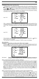
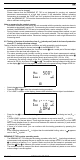
4. Unit description
See gure 1: Appliance front face
See gure 2: Top side of the device
The display and operator control elements specied in Fig. 1 and 2 are designated as follows:
1
Test socket, for connecting the device to be tested,
2
-key, testing of devices of protection class I (devices with protective conductor and
accessible conductive parts which are connected to the protective conductor),
3
-key, testing of devices of protection class II (shock-proof devices without protective
conductor and with accessible conductive parts) and testing of devices of protection class III
(safety extra-low voltage),
4
-key, testing the protective conductor current (differential measurement) or contact
current (direct measurement) under operating conditions (test sample is supplied with mains
voltage)
5
-key, reducing the testing voltage to 250 V
DC
or 500 V
DC
for measuring the insulating
resistance
6
-key, testing of 30 mA RCDs
7
-key, testing of three-phase devices under operating conditions (044140, 044141)
8
Digital display, indicates the test progress and individual measuring results,
9
4 mm test socket, for connecting the test lead with alligator clip
J
IEC connector, for connecting the IEC power cord
K
Mains connection socket, for connecting the mains voltage (230 V, 50 Hz), for voltage
measurement at external shock-proof socket or for connecting the measuring signal cable of
the measuring adapter (16 A CEE adapter, three-phase, active (044140)/ 32 A CEE adapter,
threephase, active (044141))
L
Serial PS/2 port for optional printer BENNING PT 1 (044150)
-key, for storing the displayed measured values (display values)
-key, for calling stored measured values (display values)
-key, for printing the displayed or stored measured values by means of the printer
BENNING PT 1
USB interface (Micro-B socket), for connection of the USB connecting cable
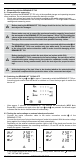
5. General information
The BENNING ST 725 is intended for electrical safety tests according to DIN VDE 0701-0702,
DGUV Regulation 3 (former BGV A3) and ÖVE/ ÖNORM E8701.
Automatically, the BENNING ST 725 veries the type of the connected test object and informs
the user in case of incorrect selection of the testing procedure [
2
...
3
]: preset limiting values and
measuring results with "pass/ fail" information make it easier to evaluate the test.
- At full battery capacity, the BENNING ST 725 allows to carry out approx. 2,500 device tests.
- Appliance dimensions:
(L x W x H) = 270 x 115 x 55 mm
- Appliance weight: 1100 g
6. Ambient conditions
- The BENNING ST 725 is intended for making measurements in dry environment.
- Maximum barometric elevation for making measurements: 2000 m,
- Over voltage category/ setting category: IEC 61010-1 → 300 V category II,
- Contamination class: 2,
- Protection class: IP 40 (DIN VDE 0470-1 IEC/ EN 60529)
IP 40 means: Protection against access to dangerous parts and protection against solid
impurities of a diameter > 1 mm, (4 - first index). No protection against water, (0 - second
index).
- EMC: EN 61326-1
- Operating temperature and relative humidity:
For operating temperatures from 0 °C to 30 °C: relative humidity less than 80 %
For operating temperatures from 31 °C to 40 °C: relative humidity less than 75 %
- Storage temperature: The BENNING ST 725 can be stored at any temperature within the
range of - 25 °C to + 65 °C (relative humidity from 0 to 80 %). The battery should be removed
from the instrument for storage.
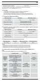
7. Electrical specifications
Note: The measuring accuracy is specied as the sum of
- a relative fraction of the measured value and
- a number of digits (i.e. counting steps of the last digit).
This specied measuring accuracy is valid for temperatures within the range of 18 °C to 28 °C
and relative humidity lower than 80 %.