
Operation Manual


03/2014
DUSPOL
®
analog
6
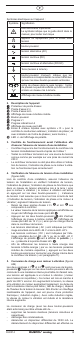
2. Device description
1
Probe tip protector
2
Probe tip L1/-
3
Probe tip L2/+
4
Plunger coil level indicator
5
Push-button
6
Handle L1
7
Display handle L2
8
LED step indicator
9
LC display mit "R" symbol für external conductor test
(phase indication) and phase sequence indicator (clock-
wise)
J +/- LEDs of the polarity indication
3. Functional test before use to ensure the absence of
voltage of an installation
- Check the voltage tester for correct functioning
immediately before and after using it!
- Test the voltage tester with familiar voltage sources, e.g.
with a 230 V socket.
- Do not use the voltage tester, if the voltage indication, the
phase indication and the vibration motor are not working
properly!
4. Checking the absence of voltage of an installation
(figure A/B)
For checking the installation, please test the absence of volt-
age by checking the voltage indication, the phase indication
(the phase indication only works in an earthed AC voltage
mains) and the vibration motor (the vibration motor is activated
by actuating both push-buttons). The installation is only free
of voltage, if all three test circuits (voltage indication, phase
indication and vibration motor) are signaling the absence of
voltage.
- Apply the two probe tips L1/+
2
and L2/-
3
to the system
parts to be tested.
- The level of voltage applied is indicated by means of the
LED step indicator
8
.
- Actuate both push-buttons
5
to connect the plunger coil
level indicator
4
, the 12 V LED step (+/ -) and an internal
load in the voltage tester.
- Alternating voltages (AC) are indicated by the +24 V LED
and the -24 V LED lighting up simultaneously.
- Direct voltages (DC) are indicated by the +24 V LED or the
-24 V LED lighting up. The polarity indication J shows the
polarity (+ or -) applied to the probe tip L2/+
3
.
- To differentiate between low-energy and high-energy volt-
ages (e.g. capacitively induced interference voltages), an
internal load in the voltage tester can be connected by ac-
tuating both push-buttons (see section 5).
5. Load connection with vibration motor (gureA/B)
Both handles L1
6
and L2
7
are equipped with push-buttons
5
. Actuate both push-buttons to switch to a lower internal re-
sistance. Here, voltage is applied to a vibration motor (motor
with unbalanced mass). From approx. 200 V on, this motor is
set in rotary motion. With the voltage increasing, the motor's
speed and vibration increases as well. The duration of the test
with a lower internal resistance (load test) depends on the level
of voltage to be measured. In order to avoid an inadmissible
warming of the device, it is provided with a thermal protection
(controlled reduction). With this controlled reduction, the speed
of the vibration motor is reduced and the internal resistance
increases.
The load connection (with both push-buttons being actuated)
can be used ...
- to suppress reactive voltages (inductive and capacitive
voltages),
- to charge capacitors,
- to trip 10/30 mA FI safety switches. The tripping of the FI
safety switch is done by testing the external conductor
(phase indication) to PE (earth). (figure D)
6. External conductor test (phase indication) (gureC)
- Fully grasp the handles L1
6
and L2
7
, in order to en-
sure a capacitive coupling to earth.
- Apply the probe tip L2/+
3
to the system part to be tested.
During the single-pole external conductor test (phase in-
dication), make absolutely sure not to touch the probe tip
L1/-
2
and that it remains contactless.
- If an "R" symbol is shown on the LC display
9
, the exter-
nal conductor (phase) of an AC voltage is applied to this
system part.
Note:
The single-pole external conductor test (phase indication)
can be carried out in an earthed mains from 230 V, 50/60 Hz
(phase to earth) on. Protective clothing and insulating condi-
tions on site might impair the function.
Attention!
The absence of voltage can only be determined by means of
a two-pole test.
7. Phase sequence test(gureE/F)
- Fully grasp both handles L1
6
and L2
7
, in order to en-
sure a capacitive coupling to earth.
-
Apply the probe tips L1/-
2
and L2/+
3
to two external
conductors (phases) of a three-phase mains (without actua-
tion the push-buttons
5
) and check whether the external
conductor voltage of e.g. 400 V is applied
.
- A clockwise phase sequence (phase L1 before phase L2)
is given, if an "R" symbol is shown on the LC display
9
.
Nothing is shown on the LC display, if no clockwise phase
sequence has been detected.
- The phase sequence test always requires a countercheck!
If the LC display shows the clockwise phase sequence by
means of the "R" symbol, the LC display must show noth-
ing during the countercheck with the probe tips L1/-
2
and L2/+
3
being inverted.