Wireless LAN Router AWL-700 User Manual Version 1.
Notice I Copyright Statement This manual cannot be reproduced in any form or by any means or used to make any derivative such as translation, transformation, or adaptation without the prior written permission of BenQ Corporation. BenQ Corporation reserves the right to change this manual and the specifications to improve products without prior notice. So you can get the most recent software and user documentation for all BenQ Wireless LAN products on our web site. http://www.BenQ.
! " # $ !%" # $ # ) *+,-.
Table of Contents Chapter 1. Introduction… … … … … … … … … … … .… … 1 1.1 Product Introduction… … … … … … … … … … … … … … … … .… … ...1 1.2 Key Features… … … … … … … … … … … … … … … .… … … 1 Chapter 2. Hardware Installation… … … … … … … … … 3 2.1 Product kit… … … … … … … … … … … … … … … … … … … … … … … 3 2.2 System Requirements… … … … … … … … … … … … … … … … … … 3 2.3 Mechanical Description… … … … … … … … … … … … … … … … … .4 2.4 ConnectAWL700 to your ADSL / Cable Modem… … … … … … .. 6 2.
Chapter 1. Introduction 1.1 Product Introduction The AWL700 Wireless LAN Router can be used with wireless networking client devices such as the BenQ AWL100 Wireless LAN PC Card and BenQ AWL300 Wireless LAN USB Adapter for wireless access to an office LAN, or sharing of an xDSL/cable modem. The AWL700 also integrates a 4-port auto-sensing crossover Ethernet switch, expanding access to already established wired networks, and allowing IP sharing without the need for additional devices.
purposes, they are also able to use those additional IP addresses to connect to the Internet. 1.2.2 Three ways to acquire WAN’s IP address There are three ways to acquire AWL700’s WAN IP address. The first one is to assign its WAN interface as a static valid IP address. Or, the users can acquire AWL700’s WAN IP address by PPPoE and it does not require the users to install PPPoE client software in their own hosts. The third one is to obtain DHCP server.
1.2.7 Firmware Upgrade AWL700 provides an efficient way to upgrade firmware. Users can use web browser to do firmware upgrades and the device also allows TFTP clients to perform this task.
Chapter 2. Hardware Installation This chapter will describe how to set up AWL700 step by step. After you have set up your AWL700 device, then you may need to configure your WAN setting to match the mode that you have applied from your ISP or NSP.
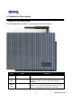
2-3 Mechanical Description Top panel of the WLAN Router The following table provides an overview of each LED activity: LED Power State On (Red) On (Green) Status WAN / LAN Link (Green) Indication When power on AWL700, this LED should always be red. When power on AWL700, AWL700 will do some initialization jobs, then this LED will be blinking steadily. When connect to the ADSL / Cable modem or connect to your PC, the LED should always be green. If this LED is not being lighted, this means link fails.
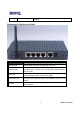
TX / RX (Orange) When data is transmitted or received, this LED will be blinking. Back panel of the Access Point: Back Panel Reset button PWR/DC jack WAN port LAN1/2/3/4 port Antenna Description Designed to reset the AWL500 after a system failure or crash. When pressed, the AWL500 will reset. Where power is input to AWL500 through the power adapter supplied with it. Please do not plug other power adapters into this jack.
2.4 Connect AWL700 to your ADSL / Cable Modem I. Turn off the power of your ADSL / Cable Modem II. Pick up the cross-over (short) RJ-45 Category-5 cable and plug one end of this cable into your ADSL / Cable’s LAN port III. Plug the other end of this cable into AWL700’s WAN port 2.5 Connecting PC/Notebook to your AWL700 Wired I. Pick up the straight (long) RJ-45 Category-5 cable and plug one end of this cable into any one of four switch ports. II.
Chapter 3. Configuration This chapter illustrates the web-based AWL700 configuration in detail. The AWL700 Wireless LAN Router has a structured menu and a “Quick Installation Wizard” page to help users set up their own AWL700 quickly. This chapter describes each of these menu sections. When the AWL700 boots up at the first time, it has a default IP address 192.168.1.1 assigned to its LAN interface. In order to configure AWL700, please point an Internet browser from the browsing host to http://192.168.1.
3.1 Quick Installation Wizard 3.1.1 WAN Parameters AWL700 provides three ways to have an IP address in its WAN interface – Fixed IP, DHCP Client, and PPPoE. There are three radio boxes in this configuration page and you can choose the one, which is suitable for your access environment. If you have applied for a dedicated IP address in your WAN side, you can choose Fixed IP mode to connect to the Internet.
Username – When you apply for a PPPoE service from your ISP, they will give you a set of username and password for the purpose of login. You can fill your username from your ISP in this input field. Password – You can fill your password from your ISP in this input field. Password Confirm – Type your password again, and this will confirm your password’s value again.
ESSID – The ESSID is a unique ID given to the Access Point. Wireless clients associating to the Access Point must have the same ESSID. The ESSID can have up to 32 characters. Channel – You may select any of the available channels as an operational channel for your Access Point. RTS Threshold – RTS Threshold is a mechanism implemented to prevent the “Hidden Node” problem. “Hidden Node” is a situation in which two stations are within range of the same Access Point, but are not within range of each other.
Select the Basic Rates to be used among the following options: 1 - 2 (Mbps), 1 2 - 5.5 – 11 (Mbps). Select the TX Rates set among the following options, (1 – 2 5.5 - 11 Mbps) or (1 - 2 Mbps). Preamble Type – Preamble is the first sub field of PPDU, which is the appropriate frame format for transmission to PHY (Physical layer). There are two options, Short Preamble and Long Preamble. 3.1.5 Remote Control Parameters AWL700 provides some remote control features to help user’s remote management for AWL700.
seconds. 3.2.2 Status In AWL700, you can search system information in “Status” page. AWL700 divides this page into two parts, one is for WAN information, and the other is for LAN information. This information is quite useful for users to see if system is in a right status. 3.2.3 Channel Info In this page, user can see the channel information of the Wireless Access Point.
3.2.4 Associated Table This is a list of all the stations that have ever associated. This table provides information to track how many stations have ever associated with the Access Point. 3.3 Advanced Setting 3.3.1 DNS Setup In “DNS Setup” page, user can input two DNS servers that AWL700 can use these two servers to complete its DNS relay function.
DNS Name Server 2 – Second backup DNS server. 3.3.2 DHCP Setup 3.3.2.1 DHCP Clone MAC Address AWL700 provides “MAC clone” function to let users change their WAN MAC address. This feature is provided for authentication purpose if your ISP would like to ask you to offer this information. Host Name – Your host’s name. MAC Address – MAC address that you want to change in your WAN interface. Generally, this MAC address will be the authenticated information to offer to your ISP or NSP. 3.3.2.
DHCP End IP – This field will be filled in automatically. 3.3.2.3 Table of fixed host entries DHCP server can assign IP addresses and some options, such as gateway’s IP address, DNS server, etc., to hosts in AWL700’s LAN interface. Usually, DHCP server assigns IP addresses dynamically. However, users can assign MAC address and IP address to be one pair.
located in the LAN interface directly because of the enabling of NAT. We could use Virtual Server to let remote hosts access internal servers. In this configuration page, you can enter a public port that is bound on a server located in the LAN interface. For example, FTP server’s public port is 21, Telnet server’s public port is 23, and HTTP server’s public port is 80. After that, you should offer a host that maps to this public port.
3.3.3.2 Dynamic NAT In the first table, you can assign a range of private IP addresses that can be converted to public ones. Base Address – The first IP address that you wish to be converted. Number of Address – Limits the range that configured by users. If you have five hosts to be converted to public IP addresses, you can limit this range to 5. In the second table, you can assign a range of public IP addresses that wait to be mapped to any private IP address at configured range in the first table.
Local Address – Local host’s IP address Global Address – The public IP address wait to be mapped to a private IP address. Please note that users could not change the first global address in the first entry because in AWL700, we can reuse the NAPT’s WAN IP address to do the static NAT conversion. 3.3.4 RIP Setup 3.3.4.1 RIP Parameters AWL700 can act as a router, which use RIP-v2 (Routing Information Protocol version 2) to exchange routing information with other RIP routers.
Network Address – Host or network that you would like to forward your packets Netmask Address – Network mask. Gateway Address – Host that you would like packets to go from. 3.3.5 Security Setup To prevent unauthorized wireless stations from accessing data transmitted over the network, the 11Mbps Wireless LAN Access Point offers WEP (Wired Equivalency Privacy). You can set up 4 encryption keys but choose one key to encrypt your data.
The 11Mbps Wireless Access Point allows you to create 4 data encryption keys to secure your data from being eavesdropped by unauthorized wireless user. To activate and set the WEP keys, do the following: From the WEP encryption item, list three options: Disable – Allows wireless adapters to communicate with Wireless Access Points without any data encryption. WEP64 – Requires wireless stations to use data encryption with 64 bits algorithm when communicating with the Wireless Access Point.
Use the following buttons to manage the Access Control Table: Enable – allow network access from stations in the list Change – to change and add the entries in the table if you enter the incorrect MAC address Delete – to remove MAC addresses one at a time NOTE Be sure to press “Apply” bottom after modifying the configuration before leave this page or “Save Setting” 3.4 Admin Password This section describes how to change the “admin” password on the AWL700 broadband sharing gateway.
New Password – Enter your new “admin” password in this field. Password can be any alphanumeric string up to 16 characters in length. Password Confirm – Reenter your “admin” password in this field to confirm it again. 3.5 Save Setting If you have already configured your AWL700 and wished to save your configuration, please select “Save Setting” page to save all your configurations.
3.7 Update Firmware AWL700 provides firmware update function by your web browser. If users would like to change their firmware version, they can do this by choosing the newer or older firmware file in their PC, then push the “Upgrade” button to begin the updating process. This progress requires one minute to complete the updating process, so AWL700 will pop up a page to ask users to wait for one minute.
3.8 Load Default Setting Every AWL700 will have its default setting when it is shipped to users. This can prevent users from corrupting the configurations and making AWL700 function abnormally. If this situation has occurred, you can go to this page and try to load AWL700’s default setting. After you have loaded the default setting of AWL700, all your previous configurations will be lost forever.
Chapter 4 Appendix TCP/IP Configuration for Windows 98/Me/2000 1. Double click Start icon, and choose the settings, then click Control Panel. 2. Double click the Network icon. See the Configuration tab, and select the TCP/IP line that has been associated to your network card. 3. Click Properties button to set the TCP/IP protocol for your AWL700 gateway. 4. Please choose one setting method from a. Fixed IP address or b. DHCP. a. Fixed IP setting: 1. Select Specify an IP address in the IP address tab.