Easy/Smart 24-port 10/100 Base-TX Ethernet Switch User’s Guide SE0224/SS0224
FCC Warning This equipment has been tested and found to comply with the limits for a Class B digital device, pursuant to Part 15 of the FCC rules. These limits are designed to provide reasonable protection against harmful interference when the equipment is operated in a residential environment. This equipment generates, uses, and can radiate radio frequency energy and, if not installed and used in accordance with this user's guide, may cause harmful interference to radio communications.
1. Introduction ............................................... 1 1.1. Product Overview .......................................................... 1 1.2. Features & Specifications ............................................... 2 1.2.1. Features ........................................................................................ 2 1.2.2. Technical Specifications ............................................................. 3 1.2.3. Physical Specifications ................................................
. Trouble Shooting .....................................36 Appendix: ...................................................... 37 Ordering Information: ..........................................................
1. Introduction 1.1. Product Overview This user’s manual describes and illustrates the installation method and usage of the 24-port Fast Ethernet Switch. The rack-mount switch (SS0224/ SE0224) introduced here provides twenty-four 10/100Mbps Fast Ethernet ports to segment traffic, extend Fast Ethernet connection distance, and convert data packets between different transmission speeds.
1.2. Features & Specifications • Compliant with IEEE 802.3 10Base-T Ethernet and 802.3u 100Base-TX Fast Ethernet Standards. • Provides 24 ports for 10Base-T/100Base-Tx, standard RJ-45 connectors. • All RJ-45 ports supports 10Base-T/100Base-Tx and Full-Duplex/HalfDuplex Auto-negotiation function. • Supports MDI/MDI-X auto crossover. • Optional up to 2 ports fiber module for 100BASE-FX multi-mode module with ST, SC, MT-RJ, or VF-45 connector, or 100BASE-FX single-mode module with SC connector.
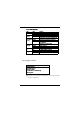
• Ethernet Standards • Protocol • 10/100Mbps Ports • Module ports IEEE 802.3 10Base-T, 802.
1.3.
'# % ( ' +-. ( '# % ( ! " # $ # % & & ) (* )+ ) ( % " # $ , ( # % . ## # / ' + '0 , 0 + . ## .
2. Installation 2.1. Operating Environment This switch must be installed and operated within the limits of specified operating temperature and humidity (see previous section under Specifications). • Do not place objects on top of the unit. • Do not obstruct any vents at the sides of the unit. • Do not position the unit near any heating source such as heater, radiator, or direct exposure to sun. • Prevent entering of water and moisture into the unit. • If necessary, use dehumidifier to reduce humidity.
2.3. Connecting the power Connect the output end of the power cord to the power connector on the rear panel of the unit. Then connect the power cord to the power outlet. The green Power LED on the front panel should be lit. 2.4. Fiber Module Installation (Optional) The fiber module is not included in the package, it’s optional. You can choose to purchase the fiber module for your switch. The fiber module shall be inserted into the expansion slot located at the rear of the switch.
• Unscrew the cover plate of the expansion slot. • Remove the plate and keep it for future use when you decide to remove the module • With the power off, slide the module into the slot • Once it is slid in fully, snap in the module to make a proper connection and fasten the screws • Then connect the module to the fiber optical cable • Turn on the power Once the power is on, the yellow F1(or F2) card exist LED on the front panel should be lit.
3. Configuration (SS0224 only) This section explains the configuration of smart switch, SS0224. For each 10/ 100Base- T/TX port, basic setting include port speed, duplex mode, flow control, auto-negotiation, etc. Other enhanced features configuration include port-based VLAN, port-based trunking, QoS, and port mirroring. 3.1.
Select Properties menu and choose Setting Page.
Check ASCII Setup menu and set.
Turn on the power of SS0224 after Hyper Terminal utility is set. If the communication is successful, user should see the main menu of console program on the screen as below: Parameters in this screen are described in the following table. Field Description Port Displays the number of the currently selected port. LINK Displays the current link status between the selected port and the connected node. This can be Up or Down.
Under this main menu of the console program, user can monitor 12 RJ-45 ports' brief status at the same page, i.e. port 1~port 12. Press [Enter] to toggle to monitor the other 12 ports, i.e. port 13~port 24. See the following figure: 3.2.
! & ! ! ! ! " # $ % % % % ' '( ! '( ) $ * + ' % $ $(+! # , , - " # . . .
3.3. Basic port-based configuration The basic configurations provided here only apply to 24 RJ-45 ports. They includes the following feature: ! In this feature, user can disable/enable selected port. And the default setting is port enabled. To enter this feature, press [E] from the main menu. For example: Select port 1 and press 'D' to disable port 1's transmit and receiving. On the contrary, user can enable it following the same policy. Refer to below figure.
auto-negotiation function, refer to the following steps: select port 2 and press [D] to disable. See the figure below. %! This feature is only used when the port's auto-negotiation function is disabled. User can force to change specific port's data rate to 10Mbps or 100Mbps.Press [R] from the main menu to enter this setting. For example: force port 3's data rate to 10Mb, refer to the figure below.
& ' ( ! Like the case in data rate setting, duplex mode setting is only changed when the corresponding port's auto-negotiation function is disabled. Press [D] from the main menu to enter this setting. For example: to set port 4 to half duplex mode, refer to the following figure. ) * ! User can set flow control capability for each RJ-45 port. Press [F] from the main menu to enter this setting. The default setting for flow control capability is enabled.
3.4. Port mirroring setting SS0224 support port mirroring function, which allows any port's ingress and/ or egress traffic to be mirrored to a pre-defined capture port. Several flexible rules can be applied to mirroring: First, for each mirror port, user can choose to mirror ingress or egress traffic or both. Second, for all the ingress mirrored packet streams, user can choose to mirror packets whose SA (source address) or DA (destination address) field is matched by a predefined MAC address.
For examples: Set port 1 as capture port and mirror both ingress and egress frames of port 2.
After choosing to mirror both ingress and egress traffic of port 2, I/E: Ingress/Egress mirror rule Configure, use this function to select mirror rules of all system. After press [I] or [E] to enter ingress/egress mirror rule configure, user can see the following items: • Press “P” to monitor all frames of all ports that are set as Ingress/Egress ports.
[S] to select source address as matched target. 3. Press [M] and enter MAC address "010203040506" 4. Press [V] to enter divider value "0x0064". Refer to the following figure: R: Reset all mirror Configure. User can use this function to disable all mirror configuration.
3.5. VLAN settings Virtual Local Area Networking (VLAN) enables efficient traffic separation, provides better bandwidth utilization, and alleviates scaling issues by logically segmenting the physical LAN so that packets are switched only between ports within the same VLAN. This also creates secure segments within the existing network. Nodes residing in different VLAN segments cannot communicate with each other although they are connected to the same switch.
Select (Y)es to reset VLAN group. At this time, no ports belong to any VLAN groups and therefore user should note that traffic between ports is disabled. In a word, the switch is disabled. After making decision about reset VLAN, user can set the VLAN groups or toggle between VLAN pages, i.e. page1~4, to check all 24 VLAN groups' status. For example, user chooses to see VLAN page3 after reset VLAN groups; refer to the following figure. 2. Select Vlan page number to see each VLAN groups' members.
3.6 QoS settings SS0224 can support port-based QoS, 802.1p compliant QoS frame. Basically, SS0224 will classify the traffic with two levels of priority, i.e. "high" or "low" priority. High priority packet streams experience less delay inside the switch, which supports certain delay-sensitive traffic, such as real-time video or VoIP streams. In this feature, user can perform the following features: • E/D: enable / disable port base qos setting. Set Enable will open all QOS Functions.
Change weight value to "a"(10), then screen will be like below figure: After press "SPACE" to return to QoS submenu, user can set the weight value for low priority by the same policy. 2. TCI THRESHOLD. Use can change the threshold for 802.1p frame. Allowable threshold value range is 0~7. If 802.1p frame pri[2:0] >= TCI THRESHOLD then it will be qualified as high priority frame.
3. Port Based Qos. In this item, user can set decided port as high or low priority port. To set Port 1 as high priority port, do the following steps: Press [P] to enter this item and press [P] to set port. Then select port 1 to set it as high priority by press [H].
Then the user can see from the below figure that port 1 has already been set as high priority: After above steps, all packets received by port 1 will be treat as high priority packets if QoS feature is enabled.
3.7 Trunking SS0224 provides port-based trunking function. The switch can support up to 12 different trunking groups. The members of each group can range from 2 to 8 and the only limitation is each trunk group can only include ports from the same chip. In SS0224, port 1 ~ port 8 belongs to chip-0, port 9 ~ port 16 belongs to chip-1, and port 17 ~ port 24 belongs to chip-2. The 2-port trunk group can provides bandwidth of up to 200Mbps, while 8-port trunk group can provides bandwidth of even 800Mbps.
Press [T] to enter trunking submenu and select chip 0. Choose enable trunking to enter trunking group and members selection. Refer to the following: Each time when user enables certain chip's trunking function, further set-up menu will show up; otherwise, the system keeps in stand-by status and waits for user to select specific chip or to exit menu. 2. Select Trunk group 5 and choose port 11, 15 as trunking ports.
Following the same policy, user can set port 15 as Trunk group 5's members. And the status should be like the following figure: 3. Set Forwarding Table. For all ports except trunking ports, they have to assign one forwarding table. The forwarding table is used to indicate which specific port in the trunk group will actually be assigned to take the traffic loading to this trunk. For the above example in chip 1's trunk setting menu, user should press [F] to set its forwarding table.
Choose port 1 and set its traffic to one of trunk group 5's member, e.g. port 11.
Following the same policy, we can choose other ports' forwarding port for this trunk group. For example, the forwarding table below shows that port 11 is forwarding port for port 1~port 10 and port 12~ port 14, while port 15 is forwarding port for port 16~port 24.
3.8 System Information In this submenu, user can perform the following features: F: Display F/W version number, which is a view-only screen showing the software version of the switch. Press [F] to show this version number. Refer to the following figure: A: Age Time, which will show current aging time and user can set new age time to this system. Besides, user can choose to disable aging function and the MAC address learned in the switch will no longer be aged.
is 4812 secs (0x12CC), and we try to change aging time to 500 seconds: refer to the following figure: B: the BIST (Burn-In Self Test) Status, which is a view-only screen showing the internal self-test (RAM, Buffer Control, packet buffer memory) during initialization/power-up.
Press [B] in this submenu, user will see the below: 3.9 Save Configuration In this submenu, user can choose to save above features configuration by item, or just save all configuration to EEPROM in SS0224.
downloaded and used as default setting for all features unless user tries to modify them. Press [S] from the main-menu to enter the Save submenu as below: SS0224 provides the following by-item configuration saving function: “P”: Save Port control configure This saving function will save basic port control functions, including port's transmit/receive enable or disable, auto negotiation ON/OFF, rate, duplexmode, and flow control capability.
user can press [P] to enable saving configuration of port control settings. See below: “A”: Save Aging time configure This will save configuration of aging time and aging enable/disable status of SS0224. “V”: Save VLAN configure This will save VLAN related configuration, including all the VLAN groups and its members. “T”: Save Trunking configure This will save Trunking related configuration, including all the Trunking groups and its corresponding forwarding table.
4. Trouble Shooting The SS0224/SE0224 can be easily monitored by its LED indicators. Please follow the troubleshooting steps below to solve any problem you may encounter during installation or implementation of the SS0224/SE0224. * Check if the power cord is properly connected to the power outlet and is firmly plugged into the power socket of the switch. + ( ,- .
Appendix: Ordering Information: Part Number 99.334N2.001 99.335N2.001 99.33228.001 99.33228.002 99.33228.003 99.33228.004 99.33228.005 99.33228.006 99.33228.
Benq Corporation (“Benq”) warrants the Benq network product you have purchased from Benq or from an Benq Authorized Reseller to be free from defects in materials and workmanship under normal use during the warranty period of one year from the date of purchase. Your original purchase invoice (sales receipt), showing the date of purchase of the network product, is your proof of the date of purchase.
work product; (b) by the use of parts not manufactured or sold by Benq; (c) by modification of the network product; (d) as a result of service by anyone other than Benq or an Benq Authorized Service Provider; (e) improper transportation or packing when returning the network product to Benq or an authorized Service Provider; or (f) unusual physical or electrical stress or interference, failure or fluctuation of electrical power, lightening, static electricity, fire or acts of God.