BenQ Solar Photovoltaic Modules Installation Guide (IEC, ETL) Mono 48 cells series PM200M00 PM200M00 / PM048M00 Poly 60 cells series PM245P00 / PM245P03 / PM060P00 Mono 60 cells series PM250M01 / PM060M02 Mono Mono 60 cells with light weight series PM060M01 Poly 72 cells series PM072P00 Back contact 96 cells series PM096B00 / PM096B01 Version 2.0 Note: The content of this manual is subject to change without notice.
BenQ Solar Photovoltaic Modules (IEC, (IEC, ETL ETL) Installation Guide for Users Table of Contents Chapter 1 General Information................................ Information ................................................................ ................................................................................................ .......................................................................... .......................................... 2 1.1 Introduction........................................
Chapter 1 General Information 1.1 Introduction The following is the product installation guide for the BenQ Solar photovoltaic modules. BenQ Solar modules should be installed by certified professionals only. This guide is designed to be used in combination with industry recognized best practices and all applicable rules and regulations. Please read these instructions in entirety before handling or using this product in any way.
1.4 Guidelines for Safe Handling and Installation IMPORTANT THIS PRODUCT IS DESIGNED DESIGNED FOR INSTALLATION INSTALLATION BY QUALIFIED PERSONNEL PERSONNEL ONLY. ALL HANDLING AND INSTALLATIONS INSTALLATIONS MUST BE PERFORMED PERFORMED IN COMPLIANCE COMPLIANCE WITH ALL APPLICABLE CODES, CODES, RULES AND REGULATIONS. REGULATIONS. In addition to the applicable rules and regulations, please follow all guidelines for safe handling and/or installation of BenQ Solar modules.
Please use caution when handling or connecting any module. Remove all metallic jewelry prior to installing this product to reduce the chance of accidental exposure to live circuits. Use properly insulated tools to reduce your risk of electric shock. During installation use suitable protection prevent a discharge of at least 30 direct current volts to each person on crew. Do not connect or disconnect modules when current from the modules or an external source is present.
STORAGE When storing modules for any period of time, cover modules to ensure protection from the elements. Take special steps to cover/protect the module connectors.. When storing the modules, turn so that the glass is face down. Do not allow water or dust to collect inside module, this can damage module connectors.
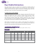
Chapter Chapter 2 BenQ Solar Module Specifications The module electrical ratings are measured under Standard Test Conditions (STC) of 1000W/m2 irradiance with AM 1.5G spectrum and a cell temperature of 25ºC. BenQ Solar modules electrical characteristics depend on module Series and Wattage. Please refer to the tables below to learn more about the characteristics of your module(s). 2.1 Performance of PV Modules A PV module may produce more current and/or voltage than reported at STC.
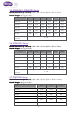
PM048M00 Power 210W 215W 220W 225W 230W 235W 240W Efficiency 16.2% 16.6% 17.0% 17.4% 17.8% 18.1% 18.5% Vmp (V) 24.3 24.4 24.5 25.0 25.1 25.15 25.23 Imp (A) 8.65 8.82 8.99 9.00 9.17 9.34 9.52 Voc (V) 30.6 30.7 30.8 31.8 32.4 32.7 33.0 Isc (A) 8.92 9.00 9.08 9.47 9.65 9.87 10.00 Maximum Tolerance 0 / +3% of Power 2.3 PM245P00 Series Module Dimensions (L x W x H): 1639 x 983 x 40 mm (64.52 x 38.7 x 1.57 in) Module Weight: 18.5 kg (41.
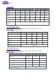
2.5 PM250M01/ PM060M02 Series Module Dimensions (L x W x H): 1639 x 983 x 40 mm (64.52 x 38.7 x 1.57 in) Module Weight: 18.5 kg (41.1 lbs) Power 265W 270W 275W 280W 285W 290W Efficiency 16.4% 16.8% 17.1% 17.4% 17.7% 18.0% Vmp (V) 31.30 31.80 32.30 32.70 31.00 31.30 Imp (A) 8.47 8.50 8.52 8.57 9.20 9.27 Voc (V) 38.2 38.5 38.7 38.9 40.0 40.4 Isc (A) 8.98 9.01 9.03 9.06 9.80 9.82 Maximum Tolerance 0 / +3% of Power 2.
2.8 PM060P00 Series Module Module Dimensions (L x W x H): 1639 x 983 x 40 mm (64.52 x 38.7 x 1.57 in) Module Weight: 18.5 kg (41.1 lbs) Power 250W 255W 260W 265W 270W Efficiency 15.5% 15.8% 16.1% 16.4% 16.7% Vmp (V) 30.6 30.8 31.2 31.6 32.0 Imp (A) 8.17 8.28 8.34 8.39 8.44 Voc (V) 37.4 37.7 37.7 37.9 38.1 Isc (A) 8.69 8.76 8.83 8.87 8.93 Maximum Tolerance of Power 0 / +3% 2.9 PM096B00 Series Module Dimensions (L x W x H): 1559 x 1046 x 46 mm (61.38 x 41.18 x 1.
Chapter 3 Mounting Mounting Guidelines Modules may be mounted at any angle from horizontal to vertical. Select the appropriate orientation to maximize sunlight exposure. A gap between the module and system structure or ground is required to prevent wire damage and to allow air to circulate behind the module. Take care to follow all applicable regulations, especially municipal and fire codes, when planning and executing your installation. Do not remove or alter the module frame.
PM096B00 Secure each module to the structure using four M6 (¼”) stainless steel bolts, with nuts, washers, and lock washers per module. Only the mounting holes that are 322mm (12.6772 inches) from the short end of the module can be used for the module to meet 5400 Pa design strength. 3.2 Mounting with Clamps • Clips and clamps are not provided by BenQ Solar. • The clamping clips on the side frame must be in parallel – equidistant from the closest module frame corner (see Figure 1).
Figure 2 Long rail mounting clamp zone (D1 and D2) Figure 3 Short rail mounting clamp zone (D3 and D4) 12
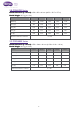
Long Rail (5400 Pa) Short Rail (2400 Pa) Model Name D1 D2 D3 D4 PM048M00 227 mm (8.94 in) 296 mm (11.65 in) 50 mm (1.97 in) 150 mm (5.91 in) PM060P00 228 mm ( 8.98 in) 428 mm (16.85 (16.85 in) 198 mm (7.8 in) 298 mm (11.73 in) PM060M01* 281 mm (11.06 (11.06 in) 375 mm (14.76 (14.76 in) * * PM060M02 228 mm ( 8.98 in) 428 mm (16.85 (16.85 in) 198 mm (7.8 in) PM072P00 127 mm (5.0 in) 300 mm (11 (11.81 in) PM096M00 250 mm (9.84 in) 400 mm (15.75 in) in) 230 mm (8 (8.46 in) 330 mm (12.
PM072P00 PM072P00 Module Clamp Location Details • Long rail clamping for 5400 Pa design strength: clamp between D1 – 127 mm (5.0 in) and D2 – 300 mm (11 (11.81 in) from the closest short side of the module. PM096B00 Module Clamp Location Details • Long rail clamping for 5400 Pa design strength: clamp between D1 – 250 mm (9.84 in) and D2 – 400 mm (15.75 in) from the closest short side of the module. • Short rail clamping for 2400 Pa design strength: clamp between D3 – 230 mm (8 (8.
Chapter 4 Wiring, Wiring, Connecting and Grounding BenQ Modules 4.1 Wiring & Connecting DO NOT make any change to the cable or Junction Box. DO NOT disconnect DC Cables alone, someone should always be nearby! DO NOT disconnect/connect modules while they are under load! DO NOT assemble the connector with wet or dirty hands. Always make sure that all locking connectors are fully engaged and locked. Otherwise faulty connetions can result in arcs, electrical shock, and equipment damage.
3. Use correctly rated materials Use PV rated solar cable for wiring and suitable connectors only. Ensure that they are in perfect electrical and mechanical condition. Use only single wire cables. Select a suitable conductor diameter to minimize voltage drop. 4. Cable protection Secure the cables to the mounting system using UV-resistant cable ties. Protect exposed cables from damage using suitable precautions. Avoid leaving DC cables in direct and extended exposure to sunlight.
• • • • • • • • Do not concentrate sunlight or other artificial light sources onto the module. Use tools duly coated with insulating material while working with the modules. Always work under dry conditions. Do not install the modules where there may be flammable gases or vapors, since sparks may be produced. Take care to avoid electric discharges when installing, wiring, starting up or carrying out maintenance work on the modules. Do not touch the terminals while the module is exposed to light.
Figure 5 Recommended grounding connection Per NEC 250.136, electrical equipment secured to and in electrical contact with a metal rack or structure provided for its support and grounded by one of the means indicated in 250.134 shall be considered effectively grounded. Failure to properly properly ground each module will reduce the performance of the system and olar’s invalidate BenQ Solar ’s Limited Power Warranty for PV Modules.
In addition, the module frame should be grounded. Failure to comply with this requirement will reduce the performance of the system and invalidate BenQ Solar Solar Limited Power Warranty for PV modules. modules. Grounding of the module frame can be achieved through use of clamps that penetrate the anodization in conjunction with grounding of the mounting system or through direct grounding of the frames by attaching a copper wire to a grounding hole of each module (bolt size, M6 × 1.0 × 50). 4.
Recommended maximum series/parallel module configurations for 1000V inverter. Maximum series = 1000V / Product Voc / 1.25 (safety factor) Example : The Voc of PM200M00_200 is 30.4V,then the maximum series/parallel module configurations for 1000V inverter is 26. Formula 1000V / 30.4V / 1.
Chapter 5 Maintenance Maintenance Inspect all modules annually for safe electrical connections, sound mechanical connection, and corrosion. BenQ Solar PV module may use Anti-Reflective Coating (ARC) glass technology to enhance power output. Do not to touch glass surface unless wearing clean gloves in order to prevent fingerprints or smudges on the ARC. Fingerprints may be removed with standard glass cleaner.
5.2 Module Cleaning Instructions Solution Mixture: clean water with low mineral amount, non-abrasive/ non-caustic detergent, weak acid/weak alkalescent solution, or solution of PH < 10. Cleaning Tool: soft brush, non-conductive brush, non-abrasive sponge, non-abrasive cloth, seamless cloth. Do not use high pressure spray. 1. Clean module and glass surface with solution and tools fitting the above descriptions. 2.
Chapter 6 Certifications Certifications 6.1 IEC Certification The PV modules provided by BenQ Solar all pass the design qualification and type approval standard IEC 61215 edition 2. The PV modules provided by BenQ Solar all pass the safety qualification standard IEC 61730 certified for application class A. Modules qualified for safety through EN IEC61730.1 and EN IEC61730.2 within this application class are considered to meet the requirements for Safety Class II. 6.