OWNER’S MANUAL Model Number 700233-1 BERCO Subframe for JOHN DEERE 300 SERIES Tractors * ASSEMBLY * REPAIR PARTS * OPERATION * MAINTENANCE CAUTION: READ & FOLLOW ALL SAFETY RULES & INSTRUCTIONS BEFORE OPERATING YOUR EQUIPMENT 104123_EN *104123_EN* 1 J-05
LIMITED WARRANTY Owner’s Responsibilities: Conditions and Products Covered: BERCOMAC guarantees any part of the product or accessory manufactured by BERCOMAC and found in the reasonable judgment of BERCOMAC to be defective in material and or workmanship will be repaired or replaced by an authorized dealer without charge up to our maximum labor rates and preestablished times. For replacement parts only standard ground freight services are covered.
TABLE OF CONTENTS INTRODUCTION ................................................................................................................................................... 2 SAFETY PRECAUTIONS ..................................................................................................................................... 3 ASSEMBLY Step 1: Subframe Installation .................................................................................................................
INTRODUCTION TO THE PURCHASER This new accessory was carefully designed to give years of dependable service. This manual has been provided to assist in the safe operation and servicing of your attachment. NOTE: All photographs and illustrations in the manual may not necessarily depict the actual models or attachment, but are intended for reference only and are based on the latest product information available at the time of publication.
SAFETY PRECAUTIONS Careful operation is your best insurance against an accident. Read this section carefully before operating the vehicle and accessory. This accessory is capable of amputating hands and feet and throwing objects. Failure to observe the following safety instructions could result in serious injury. All operators, no matter how experienced they may be, should read this and other manuals related to the vehicle and accessory before operating.
SAFETY PRECAUTIONS OPERATION: 1. 13. Keep the accessory away from heat sources or flames. Do not put hands or feet near, under or inside rotating parts. MAINTENANCE AND STORAGE 1. When cleaning, repairing or inspecting the vehicle and accessory, make certain that all moving parts have stopped. Disconnect wire from the spark plug(s) and keep wire away to prevent accidental starting. 2. Check all the bolts and components at frequent intervals to make sure that they are properly tightened. 3.
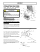
ASSEMBLY IMPORTANT: TORQUE ALL BOLTS ACCORDING TO TORQUE SPECIFICATION TABLE (SEE TABLE OF CONTENTS) WHEN STATED: TIGHTEN FIRMLY. REFER TO PARTS BREAKDOWN SECTION FOR PARTS IDENTIFICATION. WARNING TO PREVENT INJURIES: Stop the motor. Apply parking brakes. Remove the ignition key. Disconnect the wire from the spark plug(s) and keep away from spark plug(s) to prevent accidental starting. STEP 1 SUBFRAME INSTALLATION: This subframe may be used to install different attachments (see attachments page).
ASSEMBLY Adjust the overall length of the push tube (item 1) to 37 3/4" by screwing or unscrewing the adjusting rod (item 2). Place the end of the adjusting rod into the large hole of the pivot support (item 3) and secure in place with a 3mm hair pin (not shown in the ) in the hole (item 4). Install push tube Attach the spring (item 1) to the idler arm. Secure in place with a 3mm hair pin (not shown). Install the handgrip (item 3) on the idler arm.
ASSEMBLY STEP 2 SNOWBLOWER INSTALLATION: WARNING Refer to snowblower owner’s manual, parts breakdown section for parts identification. See in snowblower owner’s manual on how to modify snowblower pulley for tractors with horizontal engines. TO PREVENT INJURIES: Stop the motor. Apply parking brakes. Remove the ignition key. Disconnect the wire from the spark plug(s) and keep away from spark plug(s) to prevent accidental starting.
ASSEMBLY CAUTION Never use the snowblower without the belt guard. Remove the belt guard from the back of snowblower. Remove the hair pin (item 6). Release the tension on the belt by moving the tension arm (item 7) forward. Install the V-belt by threading it under the idler pulleys and over the engine pulley as shown. Loosen spring on tension arm Important: Make sure the belt is not twisted more than 90° and that the V part of the belt is in the V of the pulley.
ASSEMBLY Insert the handle (item 1) into the support (item 2) as shown. Install the hook (item 3) on the rotation worm (item 4). Insert the hook in the handle (item 1). Secure with a 2.5 mm hair pin (item 5). Install handle VERIFY SKID SHOE ADJUSTMENT: LEVEL PAVED SURFACE: Adjust skid shoes to allow 3/16" to 1/4" clearance (A) between cutting edge and surface. UNEVEN OR GRAVEL SURFACE: Adjust skid shoes to allow 1/2" to 5/8" clearance (A) between cutting edge and surface.
ASSEMBLY ASSEMBLY ROTARY BROOM INSTALLATION: WARNING Refer to rotary broom owner’s manual, parts breakdown section for parts identification. TO PREVENT INJURIES: Stop the motor. Apply parking brakes. Remove the ignition key. Disconnect the wire from the spark plug(s) and keep away from spark plug(s) to prevent accidental starting. WARNING FOR YOUR SECURITY: Read the rotary broom owner's manual for safety precautions and rules. Follow the assembly and operation instructions.
ASSEMBLY Remove the hair pin (item 6). Release the tension on the belt by moving the idler arm (item 7) forward. Install the V-belt by threading it under the idler pulleys and over the engine pulley as shown. Important: Make sure the belt is not twisted more than 90° and that the V part of the belt is in the V of the pulley. The back of the belt must be on the flat pulley. Apply tension on the belt by moving the tension arm (item 7) backwards.
MAINTENANCE ASSEMBLY Insert the handle (item 1) into the support (item 2) as shown. Install the handle (item 1) on the control rod (item 3) as shown and secure with a 2.5 mm hair pin (item 4). Install handle VERIFY TIRE PRESSURE: Check and adjust tractor tire pressure as follows: Front tires: Back tires: 20-25 psi 8-10 psi Tire pressure must be even on both sides of the tractor.
ASSEMBLY UTILITY BLADE INSTALLATION: Refer to Utility Blade owner’s manual, parts breakdown section for parts identification. WARNING FOR YOUR SECURITY: Read the Utility Blade owner's manual for safety precautions and rules. Follow the assembly and operation instructions. Attach the blade to the subframe as shown. Make sure the blade is pushed in until locked into place by the springs (item 1). Install utility blade Insert the handle (item 1) into the support (item 2) as shown.
MAINTENANCE & DISMOUNTING SUBFRAME DISMOUNTING WARNING See Attachment Owner’s manual (Snowblower, Rotary Broom, Utility Blade) for attachment dismounting instructions. TO PREVENT INJURIES: Stop the motor. Apply parking brakes. Remove the ignition key. Disconnect the wire from the spark plug(s) and keep away from spark plug(s) to prevent accidental starting. a) Remove the rear counterweight. b) Release tension on the belt by moving the tension arm towards the back.
TORQUE SPECIFICATION TABLE GENERAL TORQUE SPECIFICATION TABLE USE THE FOLLOWING TORQUES WHEN SPECIAL TORQUES ARE NOT GIVEN NOTE: These values apply to fasteners as received from supplier, dry or when lubricated with normal oil. They do not apply if special graphited or moly disulphide greases or other extreme pressure lubricants are used. This applies to both UNF and UNC threads. * Thick nuts must be used with grade 8 bolts SEE Grade No.
PARTS BREAKDOWN SUBFRAME 16
PARTS LIST SUBFRAME Ref. Réf. English description Description française Qty. Qté.
PARTS LIST SUBFRAME Ref. Réf. English description Description française Qty. Qté. Part # Pièce # 28 Flat pulley Poulie plate 1 102300 29 "V" Pulley Poulie en "V" 1 102086 30 Idler arm Bras de poulie 1 102314 31 Sleeve Douille 1 102322 32 Hex. bolt 3/8" n.c. x 2" Boulon hex. 3/8" n.c. x 2" 1 O/L 33 Flat washer 7/16" hole Rondelle plate 7/16" trou 7 O/L 34 Hex. bolt 3/8" n.c. x 1 3/4" Boulon hex. 3/8" n.c.
ATTACHMENTS SNOWBLOWER ROTARY TILLER #700312 Mounts to the rear of lawn & garden tractors 14 to 25 HP. Comes complete with drive & manual lift mechanisms & mounting hardware. UTILITY BLADE #700266 #700210 40" #700211 44" Mounts on the same subframe as the snowblower & rotary broom. Fits on same subframe as rotary broom and utility blade. TIRE CHAINS TRACTOR WINTER CAB #700271 ROTARY BROOM /#700316 with polypropylene brush. Fits on same subframe snowblower & utility blade. Requires an adaptor.
NOTES _____________________________________________________________________________________________ _____________________________________________________________________________________________ _____________________________________________________________________________________________ _____________________________________________________________________________________________ _____________________________________________________________________________________________ ___________________________________
NOTES _____________________________________________________________________________________________ _____________________________________________________________________________________________ _____________________________________________________________________________________________ _____________________________________________________________________________________________ _____________________________________________________________________________________________ ___________________________________
BY WHEN PERFORMANCE & DEPENDABILITY ARE NON NEGOTIABLE ! Ber comac Limitée 92, For tin Nor th, Adstock, Quebec, Canada, G0N 1S0 WWW.BERCOMAC.