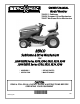
OWNER’S MANUAL Model Number 700425-1 Subframe 700426 Compact Drive Mechanism 700427 Northeast Drive Mechanism BERCO Subframe & Drive Mechanism for JOHN DEERE Series X300, X304, X320, X324, X340 JOHN DEERE Series X500, X520, X534, X540 * ASSEMBLY * REPAIR PARTS * OPERATION * MAINTENANCE CAUTION: READ & FOLLOW ALL SAFETY RULES & INSTRUCTIONS BEFORE OPERATING YOUR EQUIPMENT 104732_EN *104732_EN* 1 J-05
LIMITED WARRANTY Owner’s Responsibilities: Conditions and Products Covered: BERCOMAC guarantees any part of the product or accessory manufactured by BERCOMAC and found in the reasonable judgment of BERCOMAC to be defective in material and or workmanship will be repaired or replaced by an authorized dealer without charge up to our maximum labor rates and preestablished times. For replacement parts only standard ground freight services are covered.
TABLE OF CONTENTS PAGE INTRODUCTION .................................................................................................................................................... 2 SAFETY PRECAUTIONS ...................................................................................................................................... 3 ASSEMBLY Step 1: Subframe Installation ...................................................................................................................
INTRODUCTION TO THE PURCHASER This new accessory was carefully designed to give years of dependable service. This manual has been provided to assist in the safe operation and servicing of your attachment. NOTE: All photographs and illustrations in the manual may not necessarily depict the actual models or attachment, but are intended for reference only and are based on the latest product information available at the time of publication.
SAFETY PRECAUTIONS Careful operation is your best insurance against an accident. Read this section carefully before operating the vehicle and accessory. This accessory is capable of amputating hands and feet and throwing objects. Failure to observe the following safety instructions could result in serious injury. All operators, no matter how experienced they may be, should read this and other manuals related to the vehicle and accessory before operating.
SAFETY PRECAUTIONS OPERATION: 1. 14. Keep the accessory away from heat sources or flames. Do not put hands or feet near, under or inside rotating parts. MAINTENANCE AND STORAGE 1. When cleaning, repairing or inspecting the vehicle and accessory, make certain that all moving parts have stopped. Disconnect wire from the spark plug(s) and keep wire away to prevent accidental starting. 2. Check all the bolts and components at frequent intervals to make sure that they are properly tightened. 3.
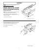
ASSEMBLY STEP 1 SUBFRAME INSTALLATION: IMPORTANT: TORQUE ALL BOLTS ACCORDING TO TORQUE SPECIFICATION TABLE (SEE TABLE OF CONTENTS) WHEN STATED: TIGHTEN FIRMLY. REFER TO PARTS BREAKDOWN SECTION FOR THEIR IDENTIFICATION. NOTE: It is recommended to remove the mower deck and it’s support before installing the subframe. Loosen the two bolts (item 1, one on each side). Reposition the panel nuts vertically (item 2, one on each side) as shown. Tighten the two bolts firmly.
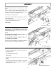
ASSEMBLY Turn the front wheels towards the right. Install the pivot support (item 1) between the two supports (items 2 & 3). Secure in place by sliding the pin (item 4) from the right side in the holes of the supports. Lock into place by placing the bended part of the pin (item 5) in the hole that is free on the right support. Secure in place with a 3 mm hair pin (item 6). Tighten firmly the lock nuts (item 7) previously installed.
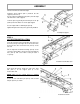
ASSEMBLY Remove the bolt (item 1) and nut from the tractor frame. Insert in order on the end of the intermediate arm (item 2): the lift support (with bushing) (item 3), the key 3/16" x 3/16" x 1 1/2" (item 4), the lift lever (item 5) and the lift stirrup (with bushing) (item 6) . Secure with a cotter pin (item 7). Secure the lift system with the bolt (item 1) and nut removed previously. In the remaining hole, insert a hex bolt 3/8" x 1 1/4" (item 8) and flange nut (item 9). Tighten firmly.
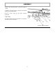
ASSEMBLY Remove the two bolts (item 1) from the right as shown. Install the cab support (item 2) under the heat shield (item 3) on the tractor frame. Secure in place with the two bolts removed previously. Tighten firmly. Screw the square head set screw 5/16" x 1/2" (item 4) into the hole of the cab support.
ASSEMBLY STEP 3 DRIVE MECHANISM INSTALLATION: NOTE: You must remove the mower deck and the front mower deck support in order to install the drive mechanism. Remove the hair pin (item 1) and pin (item 2). NOTE: There is a second hole (item 3) on the tension arm that can be used later to adjust the tension on the belt. Secure the loose end of the spring on the hook (item 4) of the drive frame.
ASSEMBLY STEP 4 LIFT ASSIST SPRING (JOHN DEERE): ADJUSTEMENT NOTE: Your John Deere tractor must be equipped with a lift assist spring (available directly from John Deere) to lift the snowblower or the rotary broom. Adjust the tension of the lift assist spring by positioning the yellow indicator (item 1) on the word “Blower”. Screw the adjustment bolt (item2) to increase tension or unscrew to decrease tension. This adjustment can be done according to your facility to lift the accessory.
ASSEMBLY STEP 5 SNOWBLOWER INSTALLATION: WARNING Refer to Snowblower owner’s manual, parts breakdown section for their identification. TO PREVENT INJURIES: Stop the motor. Apply parking brake. Remove the ignition key. Disconnect the wire from the spark plug(s) and keep away from spark plug(s) to prevent accidental starting. WARNING FOR YOUR SECURITY: Read the Snowblower’s owner's manual for safety precautions and rules. Follow the assembly and operation instructions.
ASSEMBLY VERIFY BELT ROUTING: WARNING -Remove the belt guard. -Lower the snowblower to the ground and let it run for a few seconds under supervision. -Disengage the snowblower and stop the engine. -Check the belts to make sure they are well inserted on the pulleys and have not flipped on their sides in the pulleys. -Reinstall the belt guard. TO PREVENT INJURIES: It is the person who installs the drive mechanism responsibility to make sure that when the clutch is disengaged that all moving parts stop.
ASSEMBLY STEP 6 ROTARY BROOM INSTALLATION: WARNING Refer to rotary broom owner’s manual, parts breakdown section for parts identification. TO PREVENT INJURIES: Stop the motor. Apply parking brake. Remove the ignition key. Disconnect the wire from the spark plug(s) and keep away from spark plug(s) to prevent accidental starting. WARNING FOR YOUR SECURITY: Read the Rotary Broom owner's manual for safety precautions and rules. Follow the assembly and operation instructions.
ASSEMBLY VERIFY BELT ROUTING: -Lower the rotary broom to the ground and let it run for a few seconds under supervision. -Disengage the rotary broom and stop the engine. -Check the belts to make sure they are well inserted on the pulleys and have not flipped on their sides in the pulleys and that they do not touch the belt guides WARNING TO PREVENT INJURIES: It is the person who installs the drive mechanism responsibility to make sure that when the clutch is disengaged that all moving parts stop.
ASSEMBLY STEP 7: UTILITY BLADE INSTALLATION: Refer to blade owner’s manual, parts breakdown WARNING FOR YOUR SECURITY: Read the Utility Blade owner's manual for safety precautions and rules. Follow the assembly and operation instructions. Attach the Utility Blade (item 1) to the subframe (item 2) as shown. Make sure the Utility Blade is pushed in until locked into place by the springs (item 3).
MAINTENANCE & DISMOUNTING MAINTENANCE BELT REPLACEMENT Drive Mechanism Belt: a) Check mounting bolts at frequent intervals for proper tightness to be sure equipment is in safe working condition. Before replacing the belt, check the belt tension. If necessary, secure the spring in the second hole of the idler arm. If belt tension is still insufficient, replace belt as described below. Remove the bolt that holds the idler pulley. Replace the belt and re-install the tension pulley.
TORQUE SPECIFICATION TABLE GENERAL TORQUE SPECIFICATION TABLE USE THE FOLLOWING TORQUES WHEN SPECIAL TORQUES ARE NOT GIVEN NOTE: These values apply to fasteners as received from supplier, dry or when lubricated with normal oil. They do not apply if special graphited or moly disulphide greases or other extreme pressure lubricants are used. This applies to both UNF and UNC threads. SEE Grade No.
PARTS BREAKDOWN SUBFRAME 700425-1 18
PARTS LIST SUBFRAME 700425-1 Ref. Réf. English description Description française Qty. Qté.
PARTS BREAKDOWN COMPACT DRIVE MECHANISM 700426 20
PARTS LIST COMPACT DRIVE MECHANISM 700426 Ref. Réf. English description Description française Qty. Qté. Part # Pièce # 1 Idler arm Bras de tension 1 104518 2 Flat pulley Poulie plate 1 102839 3 Flange washer Rondelle à bride 1 102969 4 Double pulley inc. 102736 & 102782 Poulie double inc.
PARTS BREAKDOWN NORTHEAST DRIVE MECHANISM 700427 22
PARTS LIST NORTHEAST DRIVE MECHANISM 700427 Ref. Réf. English description Description française Qty. Qté. Part # Pièce # 1 Idler arm Bras de tension 1 104518 2 Flat pulley Poulie plate 1 102839 3 Flange washer Rondelle à bride 1 102969 4 Double pulley inc. 102736 & 103035 Poulie double inc.
ATTACHMENTS SNOWBLOWER ROTARY TILLER #700312 Mounts to the rear of lawn & garden tractors 14 to 25 HP. Comes complete with drive & manual lift mechanisms & mounting hardware. ROTARY BROOM #700380 with nylon brush /#700381 with polypropylene brush. Fits on same subframe snowblower & utility blade. Requires an adaptor. as TRACTOR SCREEN CAB #700424 Universal type fits on a wide variety of lawn and garden tractors. UTILITY BLADE #700266 Mounts on the same subframe as the snowblower & rotary broom.
NOTES _____________________________________________________________________________________________ _____________________________________________________________________________________________ _____________________________________________________________________________________________ _____________________________________________________________________________________________ _____________________________________________________________________________________________ ___________________________________
BY WHEN PERFORMANCE & DEPENDABILITY ARE NON NEGOTIABLE ! Ber comac Limitée 92, For tin Nor th, Adstock, Quebec, Canada, G0N 1S0 WWW.BERCOMAC.