Version 1.1 December 2012 BWC EXCEL 1 48 VDC Battery Charging System Owner’s Manual EXCEL 1 Wind Turbine Bergey Windpower Co. 2200 Industrial Blvd. Norman, OK 73069 USA Telephone: (405) 364-4212 Fax: (405) 364-2078 E-mail: sales@bergey.com Web: www.bergey.
BWC EXCEL 1 Wind Turbine 48V System OWNER’S MANUAL Table of Contents 1. Overview .................................................................................................................................................. 2 2. Cautions and Warnings ............................................................................................................................ 3 3. System Description ............................................................................................................
1. Overview The BWC EXCEL 1-48 wind turbine system is a state-of-the-art small generator designed to charge batteries and supply electrical loads in a 24 to 48 VDC power system. When used in conjunction with a suitable sine wave DC-AC inverter and a 48 VDC battery bank the EXCEL 1-48 can also be connected to the power grid. The EXCEL 1-48 turbine consists of a 1kW wind turbine, a MidNite Solar Turbine Control Box and the MidNite Solar Classic 250 charge controller.
2. Cautions and Warnings This manual contains important information on the installation of your BWC EXCEL 1 wind turbine and charge controller. We strongly recommend that you read and follow the instructions contained in this manual. At several points in the manual items of special interest or significant impact are highlighted by one of the following notices. 3 DANGER: Hazard or unsafe practice that could cause personal injury or death.
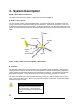
3. System Description EXCEL 1 Wind Turbine Components The major components of the EXCEL 1 wind turbine are shown in Figure 2. A. Blades / Rotor System The rotor system consists of three fiberglass blades. Acting like aircraft wings, the blades convert the energy of the wind into rotational forces that drive an alternator. The airfoil on the EXCEL 1 is the new SH3045 developed specifically for the EXCEL 1 by Bergey WindPower.
C. Nacelle The nacelle is the fiberglass housing around the main body of the machine. It contains the main structural “backbone” of the turbine (called the mainframe), the slip-ring assembly, the yaw bearings, and the tower mount. The yaw bearings allow the wind turbine to freely pivot around the top of the tower so that the rotor will face into the wind. The slip-ring assembly is the electrical connection between the moving (as it orients with the wind direction) wind turbine and the fixed tower wiring.
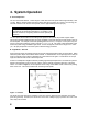
4. System Operation A. Normal Operation The rotor of the BWC EXCEL 1 should begin to rotate when the wind speed reaches approximately 3 m/s (7 mph). Battery charging should commence shortly after the rotor spins up to speed. Once turning, the rotor will continue to turn in lower wind speeds, down to approximately 2.5 m/s (6 mph). Note All operational wind speeds given assume steady winds, sealevel altitude and moderate temperatures.
But the rotor is kept facing into the wind at speeds up to ~ 12.5 m/s (28 mph) by the wind turbine’s tail assembly. The tail, in turn, is kept straight by its own weight because its pivot at the back of the nacelle is inclined. So the weight of the tail holds it against a rubber bumper and the tail holds the rotor into the wind. The geometries in the systems are carefully balanced so that at ~ 12.
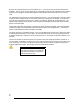
5. Turbine Installation Appendix 1 is an Installation Planning Guide. It provides recommendations on tower heights and locations, electrical components, and wiring. Please read the Appendix on “How to Avoid the Most Common Mistakes when Installing an EXCEL 1”. Tower Mounting: The EXCEL 1 wind turbine is attached to its tower by a three-sided, six fastener casting, shown in Figure 4, that is designed to fit inside a tube with an inner diameter of 108 mm (4.25 in).
Tilt-up Type Towers: If you have a tilting tower, such as the BWC Tilt Tower, the following procedure is recommended: Tools Required: 17 mm box end wrench 17 mm socket and 300mm (12”) ratchet drive 8 mm socket or wrench 4 mm Allen wrench Torque wrench (at least 50 ft-lb) Pliers Crimpers for wiring terminals (U-shaped crimp preferred over straight crimp) Thread locking compound (like Loctite 242) Tape measure, 12 ft.
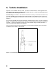
Step 2: Raise the tower about 3’ off the ground to provide room to assemble the EXCEL 1 turbine. We recommend fashioning a temporary support stand to hold the tower up during turbine assembly. Step 3: Mount the wind turbine tower adapter to the top of the tower using (6) M10-1.5 x 20mm bolts and (6) washers. Apply Loctite 242 (Thread Locking Compound) to the threads prior to installation to reduce the likelihood of loosening due to vibration.
Step 5: Place the tail boom on the rear of the turbine powerhead and insert the 12 mm tail pivot pin from the top. If the parts are aligned properly the pin should insert easily. Do not use a hammer to pound the pin in place, as this will cause scoring of the bronze bushings. Secure the tail pivot pin with the tail pivot pin collar (on top) and (2) stainless steel cotter pins, as shown in Figure 7. Note: Failure to properly install and secure both cotter pins will lead to loss of the tail boom.
Spinner Fasteners Blade Nuts & Washers Longer bolt goes here Blade Bolts Figure 8: Blade and Spinner Fasteners 3 2 1 Figure 9: Nut Tightening Order Step 7: Attach the spinner (nose cone) using the three M5 bolts and sealing washers provided, as shown in Figure 8. We recommend applying Loctite to the bolt threads prior to assembly. Step 8: Check the EXCEL 1 wind turbine carefully to make sure that the installation is complete.
Spinner is secure Tail fin is secure Tail pivot pin is locked in place with both cotter pins. Tower adapter bolts are secure Step 10: Dynamically brake the EXCEL 1’s alternator by using the shorting function of the turbine control box. Step 11: Raise the tower following the procedures outlined by the tower supplier. Please make safety your top priority.
6. Inspections and Maintenance The BWC EXCEL 1 installation should be inspected after 30 days and then again 180 days after installation. Following these two inspections the installation should be inspected every two years and after any particularly severe weather. In corrosive marine environments more frequent inspections are recommended. Inspections should be done on days when the wind is below 7 m/s (16 mph). Check List for Inspections 1) Inspect each of the anchor points.
Preventive Maintenance We recommend that the bearings be re-packed (re-greased) every 8-12 years. There are four tapered roller bearings, two for the alternator and two for the tower adapter. There are two bearing seals and we recommend that these seals be replaced when the bearings are re-packed. The strength of the blades, particularly at the root (inner) end, may degrade over time due to flexure and UV degradation of the fiberglass material.
7. Trouble-Shooting Problems The following guide can be used to pinpoint the cause of operational problems with the BWC EXCEL 1 wind turbine and the charge controller. For problems or symptoms not found in the following listing, please contact the Service Department at Bergey Windpower Co. at: Tel: (405) 364-4212 Fax: (405) 364-2078 e-mail: service@bergey.com Problem Battery voltage gets too high. Cause(s) Charge controller regulating voltage set too high Charge controller regulating voltage set too low.
8. Installation Planning Installation Planning The location and height of the tower for the BWC EXCEL 1 wind system will be important factors in determining the overall performance of the system. Average wind speed is influenced by many things and may vary considerably within a relatively small region, particularly in complex terrain. Site and tower choice, however, are often limited by such factors as zoning restrictions, property size, proximity to neighbors, customer preferences, and wiring costs.
put the turbine on your property line so that it is closer to a neighbor’s house than to your own and not give those neighbors any advance notice of your intentions. In general, we do not recommend that a BWC EXCEL 1 be installed on property of less than one acre in size. We say this because the impact of a wind turbine on the neighbors in such a “tight” area is significant and the potential for disputes is too great. If you have questions about procedures, requirements, or tactics, please contact us.
We do not recommend mounting the BWC EXCEL 1 on any home or any buildings. Our concerns are: 1. The forces on the turbine and mounting system are substantial and homes are not designed structurally for them. 2. The air flow around and over a home or building is complex and can cause considerable turbulence. 3. The wind turbine will cause vibrations that will be amplified through the home’s structure.
taken into consideration. When using a Tilt Tower you should consider the extra space needed for the tower when it is tilted down. 5. Safety The BWC EXCEL 1 should never be installed close to a power line. We recommend that the tower be at least 1 ½ times the height of the tower from any power line including any overhead service line bringing power to your home. Danger Wind turbine towers are made of metal, which readily conducts electricity.
Before assembling the wind turbine the tower wiring must be in place, though not necessarily permanently affixed. We recommend that you leave at least 30 cm (12 in) of free wire at the top of the tower for making the electrical connections to the wind turbine. E. Other System Components A complete remote power system will include other electrical components such as a battery bank (required), a solar array (optional), a dump load (optional), and an inverter (optional).
9. Specifications EXCEL 1 TURBINE: ROTOR DIAMETER OVERALL LENGTH TURBINE WEIGHT TURBINE THRUST RATED POWER RATED WINDSPEED RATED ROTOR SPEED START-UP WINDSPEED CUT-IN WINDSPEED FURLING WINDSPEED MAX DESIGN WINDSPEED MAX RUNNING CURRENT 22 Metric 2.5 m 2.1 m 34 kg 890 N Imperial 8.2 ft. 6.9 ft. 75 lbs. 200 lbs. 1,000 W 11 m/s 24.6 mph 490 rpm 3 m/s 6.7 mph 2.5 m/s 5.
10. Basic Tower Requirements Customer supplied towers for the BWC EXCEL 1 Wind Turbine should meet the following minimum requirements: Tower Height: 9 m (30 ft) minimum, though we recommend 18 m (60 ft) or higher Design Wind Speed: 54 m/s (120 mph) Turbine Weight: 34 kgs (75 lbs) Maximum Turbine Thrust Load: 890 N (200 lbs) @ 54 m/s (120 mph) Blade Clearance: Top 1.1 m (44 in) of the tower must not exceed 12.
Figure 10: Tower Adapter Requirements 24
Turbine/Tower Adapter: BWC offers a tower section that can be used with customer supplied towers. Item 6612 (10 ft) and 6612-1 (5 ft) are predrilled with the turbine mounting holes and also has guy cable attachment nuts located below the blade clearance distance.
11. System Single Line Diagram 3 x #8AWG CU + #10AWG CU GND WIRE FOR RUNS BETWEEN 180 TO 300 FEET (INCLUDING TOWER HEIGHT). REFER TO THE INSTALLATION MANUAL FOR OTHER CONFIGURATIONS AND DISTANCES. XL.1 WIND TURBINE 1kW 3Ø OUTPUT I(max) = 15A, V(max) 180VAC 6 LA 5 INDOORS 4 3 MIDNITE SOLAR TURBINE CONTROL BOX V(in) = 480VAC V(out) = 600VDC I(out) = 52A GROUND ROD AT BASE OF TOWER (OPTIONAL) OUTDOORS AC P1 INPUT P2 15A P3 CHASSIS NOTES: 15A SHORTING 1.
12. Identification Each BWC EXCEL 1-48 wind turbine has a serial number decal located on the tower mount. The Serial Number is also written on the box that the turbine came in. We recommend writing it here as well: BWC EXCEL 1-48 Serial Number: 13. Warranty FIVE YEAR BERGEY WARRANTY BWC XL.1 Windpower Generating Systems manufactured by Bergey Windpower Company, Inc.
14. Registration Card RETURN THIS CARD TO BWC ALONG WITH PHOTOS DOCUMENTING INSTALLATION NOTE: DIGITAL PHOTOGRAPHS PREFERRED IF AVAILABLE) Return to: Bergey Windpower Company 2200 Industrial Blvd. Norman, Oklahoma 73069 BWC WIND TURBINE SYSTEM REGISTRATION CARD OWNER NAME ___________________________________ Address _________________________________________ WIND SYSTEM MODEL __________________________ Serial No. (e.g.
Appendix How to Avoid the Most Common Mistakes When Installing an EXCEL 1 1. DO NOT install the wind turbine close to a steep slope or cliff. If the wind can blow up at an angle as it hits the wind turbine the furling will be hampered and the turbine will experience excessive loads and vibration. This is most important from the prevailing wind direction. Try to keep the tower at least two tower heights back from steep slopes. 2.
MNTCB Turbine Control Box Installation Instructions (continued) MNTCB Turbine Control Box The MNTCB Turbine Control Box is designed for use with three phase turbines.
MNTCB Turbine Control Box Installation Instructions (continued) IMPORTANT SAFETY INSTRUCTIONS SAVE THESE INSTRUCTIONS - These instructions contain important safety and operating instructions for the MidNite Solar MNTCB Turbine Control Box boxes. Before installing and using this product read all instructions and safety information contained in this manual.
MNTCB Turbine Control Box Installation Instructions (continued) Installation: You will need: A #2 Phillips screwdriver, #10 or larger hardware for mounting the MNTCB to the wall and a slotted screwdriver to complete wiring the MNTCB into your system. A drill may be required to drill pilot holes. The MNTCB Turbine Control Box should be located in a conveniently accessible area and secured to the wall or other mounting surface with #10 or larger screws.
MNTCB Turbine Control Box Installation Instructions (continued) DANGER: High voltage! Disconnect all sources of power before opening cover. Wiring: First verify that the turbine is stopped or disconnected and that no power is present, then, remove the desired knockout(s) on the side or bottom and route the three phase output wires from the turbine to the three box lugs just below the breakers (Page 3). Connect phase 1 to the top box lug, phase 2 to the middle box lug and phase three to the bottom box lug.
MidNite Solar Classic Owner’s Manual Standard Classic Classic Lite This Manual covers models Classic 150, 200, 250 & 250KS as well as the Classic 150, 200, 250 & 250KS LITE 1|Page
The MidNite Solar Classic charge controller conforms to UL 1741, Safety for Inverters, Converters, Controllers and Interconnection System Equipment for Use With Distributed Energy Resources, Second Edition, May 7, 1999 with revisions through January 28, 2010 and CAN/CSA C22.2 No. 107.1: 2001/09/01 Ed: 3 (R2006) Notice of Copyright MidNite Solar's Classic charge controller User’s Manual Copyright ⓒ 2010 all rights reserved. MidNite Solar Inc.
Table of Contents Glossary of Terms.....................................................................................................................................5 Scope..........................................................................................................................................................7 Introduction ..............................................................................................................................................7 Classic Power Curves ...
Viewing Other MidNite Products on the Display ............................................................................... 42 Connecting Classic to Two MNGPs/Network cable ........................................................................... 42 Arc Fault ............................................................................................................................................. 43 View Faults and Warning's .............................................................................
Glossary of Terms Absorb – Constant voltage charge stage to fill the batteries. The controller is regulating so maximum power will not be seen at this time. The Absorb timer is also counting down to the switch to Float. A-EQ-R – This will reload the Auto Equalize counters, basically it will start the counters from day 1. AF – Arc Fault, See page 43 for more info on arc fault protection. Arc Adjust – This menu is where you adjust the Arc Fault sensitivity. For info on Arc Fault see page 43.
Insomnia – This when enabled, will keep the Classic from going to Resting. This is intended for hydro mode only where you may need time to open water valves and do not want to wait for the Classic to wake up. LED-MODE – This selection lets you pick the function of the 6 visible LED’s on a standard Classic. LMX – LoMax, This enables the Classic to track the input voltage all the way down to Battery voltage. When disabled the Classic will stop tracking the input around 5 volts above the battery voltage.
Web Access – When enabled allows the Classic to send data over the internet to My MidNite’s Server for you to view when wanted. Scope This Manual provides safety guidelines and installation information for the Classic charge controller. It does not provide brand specific information about photovoltaic panels, batteries etc. Contact the manufacturer of other components in the system for relevant technical data.
•The System's DC Negative conductor must not be bonded to earth ground. The Classic does this with its internal Ground Fault Protection circuitry. The battery negative and ground are not bonded together directly but are connected together by the Classic’s internal GFP device. All negative conductor connections must be kept separate from the grounding conductor connections. The equipment ground terminal inside the Classic must be connected to Earth Ground for the internal DC-GFP to work.
ELECTRICAL SHOCK, BURN FROM HIGH SHORT CIRCUIT CURRENT, FIRE OR EXPLOSION FROM VENTED GASES. FOLLOW PROPER PRECAUTIONS. Someone should be within range of your voice to come to your aid if needed. Keep plenty of fresh water and soap nearby in case battery acid contacts skin, clothing, or eyes. Wear complete eye protection. Avoid touching eyes while working near batteries. Wash your hands with soap and warm water when done.
Figure 2.3 Figure 2.
The graphs above represent the max power output for a given input for each Classic. Using and understanding these power graphs will help maximize Classic’s output power and aid in selecting wire and breaker/disconnects. The built in set up wizard also helps select breakers and wire sizes. Notice that lower battery voltages and lower PV input voltages result in higher continuous output power. The PV voltages listed are for reference and are not intended to be the only PV voltages supported.
Removing and installing the front cover on the Classic Removing the front art deco cover is required to gain access to the wiring compartment. Be aware if this is not the first removal of this cover there is a cable connecting the cover to the electronics. Do not pull hard or fast as damage could occur. To remove the front cover of the Classic in preparation for installation, remove the 4 Phillips head screws with a #2 Phillips screwdriver. Lift the front half of the Classic casting off.
Mounting the Classic The following section covers typical mounting arrangements. If you require additional details that are not covered here please contact our technical support team. The Classic is designed to be directly mounted onto the MidNite Solar E-Panel. The Classic can also accommodate other installation methods as well. Mount in an upright position out of direct sunlight when possible. For your convenience the Classic has four one inch knock outs that are pre cast.
*Carefully hang the Classic on the screw in the bracket and slide it over the close nipple see figure 1.3. *Install the lock nut and bushing on the close nipple and tighten the screw in the mounting bracket. *Don't install the front cover until you complete the wiring of the Classic. Figure 1.3A Charge controller bracket mounted to the E-Panel. The bracket comes with every E-Panel Figure 1.3B Classic Mounted to side of E-Panel Figure 1.
Install locknut here to act as a spacer. Alternative Mounting To mount the Classic to a plywood surface use 1 1/2” wood screws in the top key hole slot hole and the holes in the wiring compartment. Taking care to make sure the Classic is Plumb and Level. Dimensions See page 70 for more details.
Sealed or Vented The Classic has the ability to be sealed for protection from salt air or dust. It comes from the factory Vented. If you live in a dusty or salt air environment you may wish to seal the Classic. Sealing the Classic does not make the unit water resistant. To seal the Classic install the solid plastic knock out covers into any unused knock outs and snap the upper vent cover onto the Classic as seen in the photo below.
Classic Stacking Cable Routing and Installation Guidelines The Classic uses a 4 conductor phone cable to communicate with other Classic's or other MidNite products. This cable is a standard 4 conductor phone cable and simply plugs into the jack on the Master Classic labeled slave. Plug the other end into the master jack on the second device (Slave). There is a plastic clamp located on the circuit board for routing the network cables above the USB jack so they stay tied down and out of the way.
Cable Clamp for network cables Battery Temp Sensor included USB connector USB cable is included Ethernet connector Figure 1.7B Battery Temperature Sensor Installation CAUTION - To reduce risk of injury, charge only deep-cycle lead acid, lead antimony, lead calcium, gel cell or absorbed glass mat type rechargeable batteries. Other types of batteries may burst, causing personal injury and damage. Never charge a frozen battery. WARNING: RISK OF INJURY.
Figure 1.8 Insert BTS to the jack labeled BATTERY TEMP on the control board. Figure 1.
Chassis Grounding In all installations the Classic chassis should be connected to ground. For systems with a battery breaker sized 60 amps and smaller 10 AWG (6 mm2) copper is generally sufficient. For systems with a battery breaker sized 100 amps and smaller 8 AWG (10 mm2) copper is required. For grounding conductor requirements on your specific installation please consult your local electrical code.
DC GFP (Ground Fault Protection) The Classic has internal ground fault protection (GFP) built in. Since 2008 the NEC requires a DC-GFP on all PV systems in the USA. The built in DC-GFP eliminates the need to purchase and install an external DC-GFP. If the internal grounding jumper is installed in a Classic, the battery negative and DC source negative must not be connected to the system grounding conductor anywhere in the system. Grounding of these circuits will defeat the GFP function.
Scroll to the right or left until TWEAKS is highlighted and press ENTER In TWEAKS press the right soft key to get to the MORE menu In MORE scroll until GFP is highlighted Use the up and down arrow keys to toggle between on and off Press ENTER to save Wiring the Classic WARNING: Shock hazard.
Figure 2.
Figure 2.
DC Terminal Connector Figure 2.4 The Classic's DC terminal connector is located on the circuit board as shown in. The connector will take up to a #4 AWG. #4 AWG THHN when installed in the Classic and MidNite E-Panel is rated for over 100 amps and is therefore suitable for the highest power available from the Classic 150.
Over Current Protection The Classic must have over current protection to protect wiring from over current events. A means of disconnect must be installed on the DC in and DC out of the Classic. Consult your local codes to determine over current ratings. The breaker between the battery bank and the Classic must conform to UL489. The breaker between the DC source and the Classic must conform to UL1077 or UL489. The NEC requires 1.56 times short circuit current for PV over current protection.
Maximum and Minimum Wire Size The Classics Blue DC terminal connector will accept wire from #14-#4 AWG The Classics Aux 1 and 2 terminal connector will accept wire up to #18 AWG 27 | P a g e
Equalization Manual and Auto Equalization with the Classic Lite 1 2 Mode 3 S1 S2 On On 4 System Voltage 5 6 Battery Type 7 8 1 EQ DHCP 2 3 4 IP Address 5 6 7 MODBUS port 8 Auto Equalize Switch 8 Equalize Manual Off Auto On By setting Auto Equalize to Manual the Equalize intervals in the Battery Settings table are effectively disabled and Equalization stages will have to be started manually. Please note that not all manufacturers recommend Equalizing AGM batteries.
Equalization with the standard Classic 29 | P a g e
Standard Classic programming Commissioning the Classic (Quick Start) The Classic will enter into the Quick Set screens upon initial power up. If the Classic does not enter into the quick set or you want to restore to Factory Default follow these steps to get initiate a Quick Set. With the power off to the Classic Hold the left and right arrow buttons down. Turn the power on to the Classic and continue to hold the arrow buttons until the setup screen is displayed.
Mode is OFF The Classic is unique, it has multiple charging algorithms for just about any DC input. Because we support such a wide variety of DC inputs we have also added a software “ON” and “OFF” feature. This software “Switch” basically turns the relay off effectively disconnecting the input source so the Classic will not charge the battery. If you see “Mode is Off” in the bottom right corner of the display then the Mode may have got turned off.
“Wizard” is highlighted. Scroll to the right until “Misc” is highlighted and press “Enter”. Now scroll to “LED-Mode” and press “Enter”. Here you can use the up and down arrows to select the mode you prefer. After selecting the appropriate LED Mode press “Enter” to save this data to the Classic. Pressing “Status” will now bring you back to the home screen. -OFF – No LED activity no matter what -Rick Mode – LED Activity for Errors and Warnings only.
The following Modes will appear in this order in the MODE Menu. Micro Hydro This mode is intended for use with hydro systems but can be used with other sources as well. When the Classic first turns on after the input voltage goes above battery voltage, it will sweep from that open circuit voltage down to battery voltage, finding the maximum power point voltage (MPP V). Then return the input to that newly found voltage.
Wind Track This mode uses a power curve that is either built by the user or one of the pre-installed graphs. The power curve consists of 16 set points that consist of output amperage and input voltage, allowing the user to custom build a curve for their Wind turbine. Please refer to the Wind section of the manual for full details on programming the curve as well as our video that will help in understanding how to adjust these curves using the wind graph editor.
Setting the Date and Time To set the date and time manually on the Classic follow the steps below. Push the Main Menu button repeatedly until Wizard is highlighted. Scroll left or right to highlight “MISC” and push the Enter button Scroll to “Time” and push Enter Now scroll left or right to highlight the data you want to manually change. Use the up and down buttons to change the data. When you have all the data changed push the Enter button to save the changes.
Main Aux Screen shows both Aux1 and Aux2 functions Off Auto On - Table 2.0 Places output to Low state (0 Volts) Selects the assigned function to the Aux output or input Sets output for Low state (12 Volts or Relay On) The Following is a list of the Aux 1 and 2 functions with brief descriptions of their function. Aux 1 Vent Fan Lo This mode will turn Aux 1 off above the voltage set point you program. It allows you to run a vent fan for a battery bank based on battery voltage.
Nite Light This mode will turn Aux 1 on at sunset and turn it off at sunrise based on the pv input voltage. Toggle Test This mode will cycle Aux 1 for 1 second off and 1 second on repeatedly. This mode is mostly for testing purposes. Pv V on Low This Mode will turn Aux 1 off above a user set voltage based on the input voltage to the Classic ( V High) and turn Aux 1 on when it hits a low voltage set point (V Low).
Low bat disc This mode will turn Aux 1 off when it reaches a set point based on battery voltage (V High) and turn it on at another set point based on battery voltage (V Low). It also allows you to set a delay time in seconds the Classic will wait before turning Aux 1 off after reaching the V High set point. It also allows you to set a hold time in seconds the Classic will wait before turning Aux 1 on after reaching the V Low set point.
Pv V on High This mode is PWM based and will PWM Aux 2 above a user set voltage (V High) based on the input voltage to the Classic and stop when it hits a low voltage set point (V Low). Toggle Test This mode will cycle Aux 2 for 1 second off and 1 second on repeatedly. This mode is mostly for testing purposes. Opportunity Lo This mode is PWM based and is just reverse logic of Opportunity Hi. It would be comparable to using the NC contacts of the relay used in Opportunity Hi.
NITE LIGHT TOGGLE TEST Pv V ON LOW Pv V ON HIGH OPPORTUNITY LO OPPURTUNITY HI LOW BAT DISC DIVERSION Aux1 on at dusk off at dawn Aux1 cycled 1 sec interval Aux1 on below Pv in setpoint Aux1 on above Pv in setpoint Divrt based on chrg state lo Divrt based on chrg state hi Disc load based on bat volt Slow Diversion control Aux 2 Function.
Setting the MNGP features The Classic comes with an integrated “MidNite Graphics Panel” (MNGP), which is the primary interface to the Classic. Setting up contrast, backlight and volume its simple just follow the steps below. Push the Main Menu button. Scroll left or right to highlight “Misc” and push the Enter button.
Below the name of the menu is a description of the menu. Pushing the left and right buttons will enable you to see all the main menus provided. Inside some of these main menus will be sub-menus to adjust the parameters of the selected feature. Here is an overview of these menus: <> Below each of the menu names is a row with a description of the menu inside. To enter a menu, the name of the menu has to be highlighted. Pushing ENTER will show the submenus.
Arc Fault The Arc Fault Detector is a unique safety component included in every Classic, because safety is not an option, the engineers at MidNite take action as the 2011 NEC code requires. The Classic is the first charge controller in the world to successfully stop a series arc. The Classic can detect an arc in less than 100mSec.
SENSITIVITY: This parameter determines how sensitive the Arc fault detector will be 1 being the most sensitive and 15 the least. This parameter is set to 10 from the factory. If you experience nuisance tripping you can raise the sensitivity one digit at a time. Follow the instructions below to make adjustments or disable Arc fault. As a last resort, you may disable Arc fault if your system cannot work with the arc fault detector.
time/date stamp for each data logging mode is Date for daily history and Time for recent history although both time and date are stored and displayed for each logging mode. When entering the "LOGS" menu, you will see two items displayed there. The top line is lifetime kWHours for the Classic and below that is time spent in float today.
The HOURLY log menu (actually captured every 5 minutes), works very similar to the DAILY log menu, except that the time stamp above the word TIME is the time, shown in 24 hour format, that the data was captured that day. The category of data captured is of course more suited for minute by minute capture rather than the maximum data statistics captured on a day by day basis in the DAILY log screen.
and the time/date stamped along with that data and does not necessarily mean the data itself is not correct. If the data is all zeros and the year is shown as 2000, the data IS most likely invalid and not correct or the logging memory has not been filled yet. This is why the Classic powers up with the year 05/04/2003...
time stamp of that data where the cursor is positioned on the graph. Finally, the bottom left of the graph screen alternates between two indicators. One is the charge stage at the cursor position and the other is the scaling of the vertical axis of the graph. Power for instance, can show a very wide range of values and power lends itself better to using a logarithmic vertical scale, shown as LOG.
Dealer Information Screen For dealers’ convenience the Classic has a display screen that can be modified to publicize the dealers’ business information. This is helpful because the customer will know who to contact in case they want to report any problems regarding the product. This will also help to promote retailers’ accessories that are compatible with the Classic. This screen is capable of 20 characters per row and four rows, for a total of 80 modifiable characters.
Classic Lite Programming The Classic Lite is based on our Classic charge controller. It has all of the same features, Power and versatility minus only the Graphic Display, and arc fault detection. It still has all of the other advanced features found in the Classic, and can be used in all of the same applications.
Programming There are four separate ways to program a Classic Lite. 1-The programming is done using Dip Switches under the front cover of the MNLP. 2-The Classic Lite can be programmed with an independent MNGP. 3-The Lite can be Networked with a standard Classic and programmed using the standard Classic’s MNGP 4-The Classic Lite can be programmed using the Local App (Through the Ethernet connection) software included on the DVD or available at www.midnitesolar.
Now you will need to use the supplied tool (Toothpick) to place all 15 switches in the correct position. All the information on the switches can be found on the labels on the MNLP as well as in the tables below. Keep in mind if any of the switches are set to Custom the Lite display becomes a LED display only and you will need to use the included PC software or a MNGP to program the Classic. Please see page XX in the Appendix for info on using the “Local App” software in conjunction with a PC.
Section 1 Switch settings explained Mode: Switches 1 and 2 (Section 1) On Section 1, the first 2 Switches are used to select which Solar Mode will be used. For “Solar” Mode: set switches 1 and 2 to OFF . This is the optimum setting for virtually all solar installations. For “Legacy “ Mode: Set Switch 1 to OFF and Switch 2 to On. Legacy Mode can be used in cases where the Open Circuit Voltage is close to the battery voltage. For example, a 22 volt open circuit array and a 12 volt battery.
Section 2 Switch settings explained DHCP or Static IP address Switch 1 (Section 2) On Section 2, Switch 1 when on will enable DHCP. This will allow the Router on the network to assign the Classic Lite an IP address. When off it sets the Classic to a static IP address that will be determined by Switches 2, 3 and 4.
Section 1 Switches 1through 8 1 2 Mode 3 Section 1 Section 2 On On 4 5 System Voltage 6 Battery Type 7 8 1 EQ DHCP 2 3 4 IP Address 5 6 7 8 MODBUS port Section 1 Mode Mode Switch 1 Switch 2 Solar Off Off Legacy Off On Reserved On Off Custom* On On System Voltage System Voltage Switch 3 Switch 4 12V Off Off 24V Off On 48V On Off Custom* On On Battery Type Switch 5 Switch 6 Switch 7 Gel Off Off Off Sealed 1 Off Off On Sealed 2 Off On Off
Section 2 Switches 1 through 7 1 2 Mode 3 Section 1 Section 2 On On 4 5 System Voltage 6 Battery Type 7 8 1 EQ DHCP 2 3 4 IP Address 5 6 7 8 MODBUS port Section 2 DHCP or Static IP address Switch 1 Static IP Off DHCP On IP Address (only if DHCP is set to Static IP) Switch 2 Switch 3 Switch 4 192.168.0.223 Off Off Off 192.168.1.223 Off Off On 192.168.1.224 Off On Off 192.168.2.223 Off On On 10.0.0.223 On Off Off 10.0.1.223 On Off On 10.0.1.
Battery voltage and time settings Battery Type Absorb Float Equalize Voltage Voltage Voltage Absorb Minimum Time (minutes) Absorb Maximum Time (minutes) Equalize Time (minutes) Equalize Interval (days)(3) 12 Volt battery Gel 14.0 13.7 - 30 90 - - Sealed 1 14.2 13.7 14.4 30 90 60 28 Sealed 2 14.3 13.7 14.6 30 90 60 28 AGM 14.4 13.7 15.1 30 120 120 28 Flooded 1 14.6 13.5 15.3 30 120 120 28 Flooded 2 14.7 13.5 15.4 30 120 120 28 Flooded 3 15.4 13.4 16.
Using MNGP Remote to program a Classic Lite The Classic Lite can be programmed using an MNGP remote. This is an easy way to get into and program not only the basic functions, but the advanced features as well. In Dip Switch Section 1set DIP Switches 1, 2, 3, and 4 to ON. This will tell the Classic Lite's MNLP display to allow custom programming, Next, remove the plug from the back of the MNLP and plug it into the MNGP. Now, you basically have a Standard Classic.
Programming the Lite with the Local App Coming Soon Clearing Faults If either the Ground Fault or Current Limit fault light is lit, then the equalize button can be tapped to clear these faults. If the fault condition has not been removed, however, then the light will re-illuminate indicating that a fault condition is still present. Notes on the Lite If anything is set to Custom, then the MNGP lite will not send any programming data to the Classic.
Uploading New Firmware to the Classic The Classic has the ability to have its firmware updated with the included USB cable and a Windows based PC. Please see www.midntesolar.com and click on the Firmware tab for the firmware and instructions. Do to the various different Windows configurations we will not go into detail in the Classic Manual. The Firmware upgrade is fail safe so if the wrong code is installed the Classic simply says “Wrong code” prompting you to load the correct code.
2. Remove the four screws holding the front cover of the Classic charge controller. Do not let the front cover hang by the cable. 3. Holding the front cover with one hand, place a screw in the top left hole of the front cover and screw it into the top right hole of the back casting.
4. Use the provided USB cable to connect the Classic to the PC. The smaller terminal connects to the USB port on the Classic. The USB port is located on the right side of the Ethernet Jack in the lower part of the Classic.
Connecting the Classic to the Internet Networking The Classic supports standard 10/100-base T Ethernet networks. For Gigabit networks you will need a common network switch that is capable of mixed mode operation. The Classic may also be placed on a, b, g, or n wireless networks by using a wireless network bridge device. Depending on your network you may use one of the topographies detailed in Figures 5 – 5.3.
Wireless Bridge Wireless Router/ Access Point Wireless enabled computer Figure 5.3 Local wireless network through wireless bridge There are many different configurations possible when it comes to networking that are beyond the scope of this manual. The basic ones in the above figures should help get you going. Network Setup Through the MNGP The Classic’s Ethernet capabilities may be configured using the Network menu on the MNGP. From the main menu select “NET”.
Please note that the Classic’s DHCP protocol implementation usually takes a few seconds up to a minute to update the network settings. If the network settings do not update within a minute, please consult the troubleshooting section. Static IP The Classic supports static IP address allocation. In this mode you can assign the Classic a specific IP address. This lets you set up things like port forwarding from your router or for networks with static IP allocations.
Web Access MidNite Solar will be offering a free web service with which you can access your Classic from a web page from anywhere in the world simply by pointing your favorite web browser to http://www.mymidnite.com See the web section further on for instructions on how to create an account and use the web-based system. All communications between the Classic and MidNite Solar’s server are encrypted using a strong sessionbased algorithm.
HyperVOC ™ HyperVOC is a unique feature the Classic has built in. HyperVOC refers to; when the DC Input Voltage raises above the maximum operating voltage (150V, 200V, 250V, depending on the Classic model). HyperVOC gives you the flexibility to go up to the maximum operating voltage PLUS the nominal battery voltage.
Troubleshooting Classic will not power on. “No self test on power up” Classic Display is blank but Classic is on. Classic says “Resting” but the sun is out? Classic switches between Resting and Bulk MPPT repeatedly but produces 0 watts. The Display shows 0 volts in (or real close) but the battery voltage looks correct. The Display is showing “Mode is Off” 68 | P a g e *Check for voltage between the Battery + and the common – on the blue terminal block inside the Classic.
Specifications Electrical Model Classic150 Classic200 Classic250 Classic250KS Operating Volts in 150VDC 200VDC 250VDC 250VDC Max Hyper VOC 150+battery 200+battery 250+battery 250+battery *Battery Charge Volts 12-93 volts 12-93 volts 12-93 volts 12-150 volts **Absolute Current Output at 25°C 96a at 12v battery 94a at 24v battery 83a at 48v battery 74a at 12v battery 70a at 24v battery 65a at 48v battery 60a at 12v battery 62a at 24v battery 55a at 48v battery 40a at 120v battery 80 a
Specifications Mechanical 70 | P a g e
Default Battery charge set points The table below describes the default preset voltages for the different nominal battery voltages. This means that if you set the Classic from the QUICK START (see page 30) to a different battery voltage the Classic will take the default voltage set points. Note. If you manually adjust the absorb float or equalize voltage set point, and then nominal battery voltage is changed to a different nominal voltage, (e.g. from 24v to 12v or to 48v etc.
Warranty MidNite Solar's Classic comes with a standard 5 year warranty we will repair or replace the Classic at no charge to the consumer during this 5 year period 72 | P a g e
Appendix Figure 3.0 Aux 1 and Aux 2 Graphs/Jumpers Figure 3.0 shows the two Aux port terminals, with their respective Polarities. These terminals are located at the bottom of the Power board below the battery temperature jack. Use a mini flat head screw driver to tighten the screws. The jumpers are described in the section below.
Aux 1 Voltage-Time Relation (Relay/12v) Aux 1 Function Graph shows the relationship between voltage and time of AUX 1. (The axis labeled VOLTAGE could be battery, PV, wind input voltage, etc.
Classic Breaker sizing 75 | P a g e
76 | P a g e
Label Set from Classic 77 | P a g e
MODBUS DISCLAIMER There is not a convention on the write-ability of registers. You may write to any register in the system including registers THAT MAY DAMAGE OR DESTROY your Classic and attached equipment like battery banks. Please make sure that you understand what you are doing before attempting to change any settings (like battery voltage) using the raw MODBUS interface. MidNite Solar cannot take responsibility for any damage to your Classic in the event of misconfiguration.
MODBUS application has reason to reset or adjust this register, there is nothing to prevent you from changing it however you please. Don’t be surprised if your batteries pop in and out of Absorb stage unexpectedly, though! Operators: Indexing [] square brackets around an address indicate the value of the register specified: ex: [4116] indicates the value of the register at address 4116. [ ]MSB Square brackets followed by an MSB means to use the most-significant byte of the register.
<< x >> x | & ^ String || Binary shift left. Shift the value x binary digits to the left. This is equivalent to multiplying the decimal number by 2x. Ex: [4116] = 0x0001 Then [4116] << 1 = 0x0002. Binary shift right. Shift the value x binary digits to the right. This is equivalent to dividing the decimal number by 2x. [4116] = 0x0002 Then [4116] >> 1 = 0x0001. OR two numbers together (aligned to LSB) AND two numbers together (aligned to LSB) XOR two numbers together (aligned to LSB) Concatenate.
Base Registers Address R/W Name Conversion Notes 4101 R UNIT_ID PCB revision = [4101]MSB Unit Type = [4101]LSB The PCB revision is a value between 0 and 255 indicating the hardware revision of the PC board. The Unit Type is an integer value indicating the voltage category of the Classic See Table 4101-1. 4102 4103 R UNIT_SW_DATE_RO Year = [4102] Month = [4103]MSB Day = [4103]LSB Software Build date.
Address R/W Name Conversion 4123 Notes RESERVED 4124 R MatchPointShadow [4124] Instantaneous value of Wind curve being used.
Address R/W Name Conversion Notes 4147 R NoDoubleClickTimer [4142] Seconds Forced time space between manual MPPT sweeps. 4148 R/W Battery output Current Limit [4148] / 10) Amps Battery Current Limit Amps (example: 23.4 A = 234) 4149 R/W Absorb Set Point Voltage ([4149] / 10) Volts Battery Absorb Stage Set point Voltage (example: 28.
Address R/W Name Conversion Notes 4162 R/W Equalize Time [4162] Seconds Initialize Time for Batteries to remain in Equalize Stage. 4163 R/W Equalize Interval Days [4163] Days Number of days between Equalize Stages (Auto EQ) 4164 R/W Mppt Mode (Solar, Wind, …………… etc) [4164] (bit 0 = On/Off) Maximum Power Point Mode. See Table 4164-1. 4165 R/W Aux 1 and 2 Function [4165] Combined Aux 1&2 Functions + On/Off.
Address R/W 4179 Name R/W Aux1VoltsHiPv (absolute) 4180 4181 ([4179] /10) Volts Notes Aux 1 High PV Voltage Threshold RESERVED (Do NOT Write) R/W Aux2VoltsHiPv (absolute) 4182 4183 Conversion ([4181] /10) Volts Aux 2 High PV Voltage Threshold RESERVED (Do NOT Write) R/W ArcFaultSenstvty Time = [4183] Sense = [4183] Arc Fault Protection sensitivity response adjustments 4184 4185 RESERVED (Do NOT Write) 4186 4187 R/W Enable Flags bits [4187] See Table 4187-1 4188 R/W RESERVED [4188] RES
Address R/W Name Conversion Notes 4202 R/W ClipperCmdVolts ([4202] /10) Volts Variable Voltage command to Clipper or Aux in Clipper mode 4203 R/W WindNumberOfPoles [4203] poles Number of turbine alternator poles (for RPM Calc) 4204 R/W MppPercentVoc [4204] 00 to 100 % % of Voc for U-Set mode 4205 R/W WindTableToUse [4205] FUTURE power curve select 4206 R/W WindTableLearn [4206] FUTURE Wind Learn usage 4207 R/W LEDmode [4207] See Table 4207-1 4208 4209 RESERVED 4210 4211 4212 42
Address R/W Name 4225 4226 Conversion Notes RESERVED (Do NOT Write) R/W VauxA2Dinput [4226] TBD Aux 2 A to D input (TBD) 4227 4228 RESERVED (Do NOT Write) 4229 4230 4231 R VocRD ([4231] /10) Volts Last VOC reading 4232 4233 RESERVED (Do NOT Write) 4234 4235 4236 R/W AbsorbTime [4236] seconds Absorb Time Counter (DUP!) 4237 R/W AntiClickSenstvty [4237] Best Left Alone 4238 SiestaTime [4238] seconds Sleep timer 4239 SiestaAbortVocAdj ([4239] / 10) Volts Volts above last Voc rea
Address R/W Name 4251 R BattMonSOC 4252 R BattMonAmps 4253 R BattMonAHefficiency Conversion Notes 4254 RESERVED (Do NOT Write) 4255 4256 4257 R/W RebulkTimerSec 4258 4259 4260 4261 4262 4263 Rebulk interval timer.
4279 Address R/W 4280 Name Typeint Conversion Notes ([4279] << 16) + [4278] TBD 4281 4282 RESERVED (Do NOT Write) 4283 Table 4101-1 Device Type Name Classic150 Classic200 Classic250 Classic250 KS Value 150 200 250 251 Description Classic 150 Classic 200 Classic 250 Classic 250 with 120 V Battery bank capability (lower current than 250) Table 4120-1 Battery Stage (UPPER Byte of mbComboChrgStge register) Name Resting Absorb BulkMppt Value 0 3 4 Description Off , No Power, Waiting for Power Sourc
Table 4130-1 Info Flag Bits: READ ONLY Flag Classic Over Temperature EEPROM error RESERVED Equalize In Progress RESERVED RESERVED RESERVED EQ MPPT Value 0x00000001 0x00000002 0x00000004 0x00000008 0x00000010 0x00000020 0x00000040 0x00000080 Description Classic Over Temperature if set Classic EEprom read/write found an error if set RESERVED Equalize Charge stage Active if set RESERVED RESERVED RESERVED In V is Lower Than Out 0x00000100 Input Voltage (PV) is lower than Vbatt if set Current Limit HyperVo
Table 4158-1 Battery Type (not used yet as of May 2011) Name Flooded Gel AGM AGM2 Lithium Nicad VRLA AbsolyteIIP User1 Value 1 2 3 4 5 6 7 8 9 Description Lead Acid (Flooded) Lead Acid (Gel) Lead Acid (AGM) Lead Acid (AGM2) LiIon Nickel Cadmium AGM or AGM or AGM2 actually TBD TBD Table 4160-1 ForceFlagsBits (can write to low or high 16 bits independently if wanted) Name RESERVED ForceRstDailyKwHrsF ForceEEpromUpdateWriteF ForceEEpromInitReadF Value 0x00000001 0x00000002 0x00000004 0x00000008 Descriptio
Table 4164-1 MPPT MODE† ` PV_Uset Value 0x0001 Description U-SET MPPT MODE (includes MPPT ENABLED (On) FLAG i.e.
Table 4240-1 Internal Flags bits (Read Only) (flagsRD) Name Value Description 0x00000001 RESERVED RESERVED 0x00000002 RESERVED RESERVED 0x00000004 RESERVED RESERVED 0x00000008 RESERVED RESERVED 0x00000010 RESERVED RESERVED 0x00000020 RESERVED RESERVED 0x00000040 RESERVED RESERVED AbsorbTimeRunf 0x00000080 Bulk/Absorb Timer Counting is Enabled EqTimeRunf 0x00000100 EQualize Timer Run flag FloatTimeRunf 0x00000200 Float Time accumulate flag kWhAccumRunf 0x00000400 kiloWatt-hour & Amp-Hour accumulate enabled 0
AUX 1 and 2 modes Extracted and encoded as combined in Aux12Function Table 4165-1 AUX 1 Off – Auto – On (Extracted/Encoded as Aux12Function bits 6,7) Name Value Description Aux 1 Off 0 Aux 1 output is OFF (0 Volts) Aux 1 Auto 1 Aux 1 operates as defined in Aux2Funtion Aux 1 On 2 Aux 1 output is ON (~14 Volts) Aux 1 Unimplemented 3 Unassigned at present Aux1OffAutoOn = (((Aux12Function & 0xc0) >> 6)); Table 4165-2 AUX 2 Off – Auto – On (Extracted/Encoded as Aux12Function bits 14,15) Name Value Description Au
Table 4165-4 AUX 2 Function (Extracted/Encoded as Aux12Function bits 8-13) Name Value Description DIVERT DGTL F+ 0 Digital Out PWM Battery Diversion (Active High) DIVERT DGTL F1 Digital Out PWM Battery Diversion (Active Low) BAT DIV V REL+ 2 Digital Out PWM Relative to Charge Stage Voltage Threshold Diversion (Use It Or Lose It) (Active High) BAT DIV V REL3 Digital Out PWM Relative to Charge Stage Voltage Threshold Diversion (Use It Or Lose It) (Active Low) TOGGLE TEST 6 Out Once per second On-Off-On-Off au
Table 4214-1 Consolidated Time Registers 0 (write only to set Classic Time -- Normally, MNGP will set these registers from its battery backed RTC) Name Value Description BITS 5:0 0 to 59 Seconds Seconds value in the range of 0 to 59 BITS 5:0 RESERVED RESERVED (Do NOT write ones to these bits) BITS 13:8 0 to 59 Minutes value in the range of 0 to 59 BITS 15:14 RESERVED RESERVED (Do NOT write ones to these bits) BITS 20:16 0 to 23 Hours value in the range of 0 to 23 BITS 23:21 RESERVED RESERVED (Do NOT write o
Table 4275-1 Reason For Resting VALUE REASON FOR RESTING 1 Anti-Click. Not enough power available (Wake Up) 2 Insane Ibatt Measurement (Wake Up) 3 Negative Current (load on PV input ?) (Wake Up) 4 PV Input Voltage lower than Battery V (Vreg state) 5 Too low of power out and Vbatt below set point for > 90 seconds 6 FET temperature too high (always shows up on boot up) (Cover is on maybe ?) 7 Ground Fault Detected 8 Arc Fault Detected 9 Too much negative current while operating 10 Battery is less than 8.
The network registers are all Read/Write. You may write any values to these registers, however this may result in erratic operation in some instances. To set A static IP address, be sure to clear the DHCP bit in register 20481 before writing the static values to the Network Address Name Units Description 20481 IP Settings [20481] Network Settings Flags. See Table 20481-1 20482 20483 IP Address [20483]MSB . [20483]LSB . The IP address of the [20482]MSB .
The Version Registers are all Read Only. Writes to any of these registers will have no long-term effect.
Communication Statistics are all Read/Write registers. You may write any value to these registers which will be incremented should the trigger for that counter occur. The most useful type of write may be to periodically reset the counters to zero. These are all lifetime counters and due to the number of MODBUS transactions may overflow to 0.
Communication Statistics Remote bus interface 10033 10034 rx_ok ([10034] << 16) + [10033] Number of correctly received packets 10035 10036 rx_crc_err ([10036] << 16) + [10035] Number of packets received with crc errors 10037 10038 requested_ok ([10038] << 16) + [10037] Number of transactions originating from this unit that completed successfully 10039 10040 requested_err ([10040] << 16) + [10039] Number of transactions originating from this unit that failed 10041 10042 forwarded ([10042] <
Reserved Address 6144161442 Name Reserved units Description Reserved RS232 Jack Pin Out Figure 1.