
Owner`s manual


4
3. System Description
EXCEL 1 Wind Turbine Components
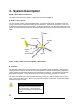
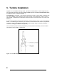
The major components of the EXCEL 1 wind turbine are shown in Figure 2.
A. Blades / Rotor System
The rotor system consists of three fiberglass blades. Acting like aircraft wings, the blades convert the
energy of the wind into rotational forces that drive an alternator. The airfoil on the EXCEL 1 is the new
SH3045 developed specifically for the EXCEL 1 by Bergey WindPower. The fiberglass blades are excep-
tionally strong because they are densely packed with glass reinforcing fibers that run the full length of the
blade.
Figure 2: Major Components of the EXCEL 1 Wind Turbine
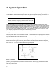
B. Alternator
The alternator rotates from torque generated by the rotor blades to produce electricity. The alternator
utilizes permanent magnets and has an inverted configuration in that the outside housing (magnet can)
rotates, while the internal stator windings and central shaft are stationary. The alternator was specially
designed for the EXCEL 1 and produces power at low RPM’s, eliminating the need for a gearbox.
The output from the alternator is three-phase alternating current (AC), and is rectified to direct current
(DC) to charge the battery bank. Since it uses permanent magnets, the alternator is generating voltage
whenever the rotor is turning.
Danger
The output wiring of the BWC EXCEL 1-
48 presents a shock hazard whenever
the rotor is turning. Caution must be
exercised at all times to avoid electrical
shock.
A
lternator
Powerhead
Tail Fin
Tower
Mount/Adapter
Spinner
Blades
Nacelle