Version 2.2 August 2003 BWC XL.1 24 VDC Battery Charging System Owners Manual XL.1 Wind Turbine PowerCenter Controller Bergey Windpower Co. 2001 Priestley Ave., Norman, OK 73069 USA Telephone: (405) 364-4212 Fax: (405) 364-2078 E-mail: sales@bergey.com Web: www.bergey.
BWC XL.1 Wind Turbine 24V Battery Charging System OWNERS MANUAL Table of Contents 1. 2. 3. 4. 5. 6. 7. 8. 9. Overview ……………………... Cautions and Warnings …….. Identification …………………. System Description ………... System Operation ………….. Turbine Installation ………. PowerCenter Installation ….. Inspections and Maintenance Trouble-Shooting ………….. Installation Planning ………… Common Mistakes ………….. XL.1 Specifications …………. Basic Tower Requirements ..
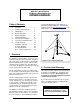
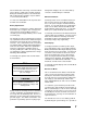
Caution Powerhead Tail Fin Hazards or unsafe practices that could cause product damage. Nacelle Alternator Blades Spinner Note Tail Boom Significant points of interest 3. Identification Each BWC XL.1-24 wind turbine has a serial number decal located on the tower mount. The Serial Number is also written on the box that the turbine came in. We recommend writing it here as well BWC XL.1-24 Serial No.: 4. System Description XL.1 Wind Turbine Components Figure 2, Major Components of the XL.
bearings allow the wind turbine to freely pivot around the top of the tower so that the rotor will face into the wind. The slip-ring assembly is the electrical connection between the moving (as it orients with the wind direction) wind turbine and the fixed tower wiring. The slip-rings and yaw bearings are located just above the tower mount. The tower mount attaches the XL.1 turbine to the top of the tower. D.
wind speed doubles from 5 m/s (11.2 mph) to 10 m/s (22.4 m/s), the energy in the wind increases by a factor of eight (23 = 2 x 2 x 2 = 8). One result of this relationship is that there is very little energy available in light winds. For the average site, winds in the range of 5.5 – 9 m/s (12 – 20 mph) will provide most of the system’s annual energy production. B. High Winds - AutoFurl During periods of high wind speeds the AutoFurl system will automatically protect the wind turbine.
optional Extra Load (or “dump load”). The Extra Load function diverts current from the battery to an air or water heater. If this measure is not sufficient, or there is no dump load in the system, the PowerCenter will slow the wind turbine and pulse the solar panels on and off to regulate the charge on the batteries. Slow-Mode prevents the wind turbine from operating without load once the batteries are full. This reduces noise and reduces the likelihood of blade flutter.
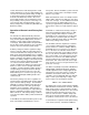
button during this time period applies electrical braking for Stop Mode. Approximate Battery Reserve Below 5% LED No. (from left side) L1 (red) Indicated Battery Voltage Range Below 22 V L2 (yellow) 22 – 23.5 V 5% L3 (green) 23.5 – 24 V 15% L4 (green) 24 – 24.5 V 30% L5 (green) L6 (green) 24.5 – 25 V 25 – 27 V 60% 90% L7 (green) 27 – 28 V 100% L8 (green) 28 – 29.5 V 100% L9 (yellow) 29.5 – 30.5 V 100% L10 (red) Above 30.
If the PowerCenter cannot stop or slow the turbine after 3 minutes, it will return to normal operation. During the following 5 minutes, the PowerCenter will not allow another attempt to stop the turbine or enter manual Slow Mode. during hard charging is the reason that battery enclosures should always be ventilated. To release the wind turbine from stop mode click the Mode Selector Button.
fool the PowerCenter if the battery bank is small and the wind gusts are strong. High charging current can raise the battery bank voltage too high for a short period (several seconds) and put the PowerCenter into Blown Fuse Mode. We recommend a battery bank of at least 220 Ah to avoid this possibility. Also if you have a PV array or inverter-charger that could momentarily create a battery voltage above 35 VDC they will initiate the Blown Fuse Mode.
above and then calculate the required wattage. It is recommended that the dissipation rating be at least 10% higher than this figure: If a different regulation voltage is necessary based upon the battery manufacturer’s recommendations, the following procedure allows easy adjustment. WATTAGE = AMPS x AMPS x RESISTANCE Caution Do not connect too large of an Extra Load (greater than 60 amps). The PowerCenter may be damaged.
propriate ring terminals. Attach the two power conductors to the slip-ring assembly with the screws provided. The polarities of the connections are marked. If your conductors are colorcoded we recommend making note of the colors connected to positive and negative leads. Caution Do not use the box lugs supplied for the PowerCenter connections instead of ring terminals. The box lugs could short circuit against the tower tube and damage the alternator. Caution Figure 6, Tower Mounting for the XL.
tener torque on the tower mounting bolts. The recommended torque is 54 N.m (40 ft-lbs). this check. Carefully mark the positive and negative electrical leads for later reference. We recommend that you connect the battery bank to the PowerCenter at this point so that you can use the Stop Mode to keep the blades from turning during the turbine and tower raising process.
Step 6: Place the tail boom on the rear of the turbine powerhead and insert the 12 mm (1/2”) tail pivot pin from the top. If the parts are aligned properly the pin should insert easily. Do not use a hammer to pound the pin in place, as this may cause scoring of the bronze bushings. Secure the tail pivot pin with two flat washers and cotter pins, as shown in Figure 9. Note: Failure to properly install and secure both cotter pins will lead to loss of the tail boom.
Step 9: Check the XL.1 wind turbine carefully to make sure that the installation is complete. We recommend the following checklist: Blade fasteners are secure and properly torqued Blade tips are evenly spaced Spinner is secure Tail fin is secure Tail pivot pin is locked in place with both cotter pins. Tower adapter bolts are secure Wiring polarity is tested and marked Step 10: Dynamically brake the XL.
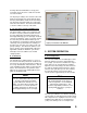
7. PowerCenter Installation A. Electrical System The general electrical configuration for BWC XL.1 and hybrid system installations is shown in Figure 11. In most cases the loads will be AC (alternating current) and they will be supplied through a DC-to-AC inverter. DC Wire Run (Tower & PowerCenter Ground) Alternator PV Array Rectifier (on turbine) The PowerCenter must be installed indoors and should be located relatively close to the battery bank.
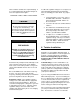
recommend a Delta LA302DC arrestor installed into the third (from the left) rear entrance hole of the enclosure. This tucks the arrestor neatly behind the enclosure. The arrestor leads are connected to the wind turbine terminals. Enclosure Dimensions 337 mm 13 1/4“ 13.25“ Front View 128 mm 5.0“ Bottom View 390 mm 15 3/8“ 15.
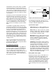
The specifications for the dump load are explained on page 8. If you have already connected the wind turbine and battery bank following the recommended procedure for installing the wind turbine, you can go to Step 5. Figure 13, PowerCenter with Cover Removed We recommend the following procedure for making the electrical connections. Please ensure that the wires do not pull on, or flex, the circuit board. Step 1: Remove the cover to expose the circuit board and terminals.
Before continuing with the install, click the mode selector button to stop the turbine, and prevent the dump load from being energized. Step 8: Click the mode selector button to release the turbine, and begin operating the turbine. Step 5: Connect PV leads. Please ensure that the PV leads are connected with the proper polarity. The system will not operate correctly and could be damaged if the polarity is reversed.
4. Remove the spinner. Check the torque on the blade nuts; the recommended value is 54 N.m (40 ft-lbs). Check the front bearing cover for seal integrity and grease loss. Check the alternator bearings for lack of play, a tiny amount of play is acceptable and normal, if it appears excessive, pop the front bearing cover off. This will expose the bearing adjustment nut. Remove the cotter pin and tighten the nut to just snug.
9. Trouble-Shooting Problems The following guide can be used to pinpoint the cause of operational problems with the BWC XL.1 wind turbine and the PowerCenter controller. For problems or symptoms not found in the following listing, please contact the Service Department at Bergey Windpower Co. at: Tel: 405-364-4212 Fax: 405 364-2078 e-mail: pieter@bergey.com PROBLEM Battery voltage gets too high. Batteries do not reach full state of charge.
PROBLEM Rotor turns, but the system doesn’t charge the batteries. Rotor is unbalanced, causing the turbine to move slightly back and forth as it spins. Wind is higher than 16 mph, but rotor will not turn, or turns slowly CAUSE(S) DIAGNOSIS REMEDY Blown Turbine fuse Check voltage across fuse with turbine spinning, should be near zero volts DC.
Disconnect turbine and check with diode meter. Should read ~ “1 V” in one direction and “OL” in the other direction. PROBLEM PV is not on, even though sun is shining. Dump load does not work. Dump load comes on during automatic generator charge, preventing the batteries from taking a bulk charge CAUSE(S) DIAGNOSIS Replace rectifier. REMEDY Dump load at 97% capacity or higher Turn on additional loads to pull down battery voltage. See if PV turns on. Normal operation. PV hooked up backwards.
Appendices 22
Appendix 1 Installation Planning The location and height of the tower for the BWC XL.1 wind system will be important factors in determining the overall performance of the system. Average wind speed is influenced by many things and may vary considerably within a relatively small region, particularly in complex terrain. Site and tower choice, however, are often limited by such factors as zoning restrictions, property size, proximity to neighbors, customer preferences, and wiring costs.
wind systems have been installed and communities are generally unfamiliar with them, you may face some obstacles in gaining permission to install a unit. We appreciate the pioneering spirit and resolve demonstrated by our customers and we stand ready to help out in any way that we can. B. Towers The smooth flow of the wind over the land is interrupted by obstructions and topographical variations. These interruptions bring about two important phenomena: wind shear and turbulence.
sites. In choosing the best one, the following factors should be considered: 1. The proximity of the proposed site to dwellings. As noted before, it is a good idea for you to consult with neighbors about the installation before proceeding. The rotor system and alternator do produce a certain amount of sound. This is a low-level whirring sound that usually can not be heard indoors. From a noise standpoint, the further the wind turbine is from a house the better.
good abrasion resistance. For ground runs we recommend THHN wire buried inside plastic conduit rated for electrical service. A suitable watertight junction box should be installed at the base of the tower to enclose the wire connections between the tower and underground wiring. In some cases it will be possible to provide direct point-to-point wiring between the XL.1 wind turbine and the PowerCenter.
step in charging current rather than several smaller ones.
How to Avoid the 6 Most Common Mistakes when Installing an XL.1 1. DO NOT use the PowerCenter box lugs to connect wiring to the turbine. There is not enough space for them, so they will rub the tower and eventually develop a short circuit. Use crimp-type ring lugs. Use These Not These 2. DO use the built-in polarity checker when connecting the battery leads to the PowerCenter. Connect either battery lead to the Neg.
Appendix 2 XL.1 SPECIFICATIONS TURBINE: ROTOR DIAMETER OVERALL LENGTH TURBINE WEIGHT TURBINE THRUST RATED POWER RATED WINDSPEED RATED ROTOR SPEED START-UP WINDSPEED CUT-IN WINDSPEED FURLING WINDSPEED MAX DESIGN WINDSPEED MAX RUNNING CURRENT MAX SHORT CIRCUIT CURRENT 2.5 M 2.1 M 34 KG 890 N 8.2 FT 6.9 FT 75 LB 200 LB 1,000 W 11 M/S 24.6 MPH 490 RPM 3 M/S 6.7 MPH 2.5 M/S 5.
Appendix 3 BASIC TOWER REQUIREMENTS For the BWC XL.1 Wind Turbine Customer supplied towers for the BWC XL.1 Wind Turbine should meet the following minimum requirements: Tower Height: 9 m (30 ft) minimum, though we recommend 18 m (60 ft) or higher Design Wind Speed: 54 m/s (120 mph) Turbine Weight: 34 kgs (75 lbs) Maximum Turbine Thrust Load: 890 N (200 lbs) @ 54 m/s (120 mph) Blade Clearance: Top 1.1 m (44 in) of the tower must not exceed 12.
31