
Specifications


9
above and then calculate the required wattage. It
is recommended that the dissipation rating be at
least 10% higher than this figure:
WATTAGE = AMPS x AMPS x RESISTANCE
Caution
Do not connect too large of an Extra
Load (greater than 60 amps). The
PowerCenter may be damaged. If you
do not understand the above equations,
please call Bergey Windpower for assis-
tance.
Warning
FIRE HAZARD
DO NOT use a dump load that is not
safely isolated from all potential
sources of combustible materials or
fuels, including wood mounting
boards and hydrogen out-gassing
from the batteries.
Put another way a dump load rated 60 amps at 30
volts is the largest that can be used. Multiple
loads can be connected in parallel as long as the
sum of their individual currents does not exceed
60 amps.
Due to the PWM feature some Extra Loads may
be noisy. The noise comes from the high-
frequency switching and it will only be heard when
power is being delivered to the dump load.
Regulation voltage: The regulation voltage is
factory preset at 28.1 VDC, which is appropriate
for flooded-cell lead-acid batteries. We do not
recommend changing this setting unless you have
a compelling reason to do so. Improper voltage
regulation settings can lead to either under-
charging and shorter battery life or over-charging
and shorter battery life.
If a different regulation voltage is necessary based
upon the battery manufacturer’s recommenda-
tions, the following procedure allows easy adjust-
ment.
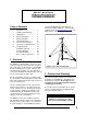
1. Using a multi-meter set to volts, connect
the black lead to the “BAT –“ terminal, or
touch the terminal marked “TEST 2” on
the circuit board.
2. Touch the red lead to the terminal marked
“TEST 1”.
3. The multi-meter should indicate the regu-
lation voltage divided by 10; for instance,
the factory setting is 28.1 VDC, so on
“TEST 1” you will read 2.810 VDC.
4. To adjust, use a screwdriver to turn the
trim pot labeled “R501”. To increase the
regulation voltage, turn the pot clockwise.
Check the voltage on “TEST 1” and adjust
R501 until “TEST 1” reads the desired
regulation voltage divided by 10.
6. Turbine Installation
Appendix 1 is an Installation Planning Guide. It
provides recommendations on tower heights and
locations, electrical components, and wiring.
Please read the Appendix page on “How to
Avoid the 6 Most Common Mistakes when In-
stalling an XL.1”.
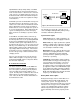
Tower Mounting: The XL.1 wind turbine is at-
tached to its tower by a three-sided, six fastener
casting, shown in Figure 6, that is designed to fit
inside a tube with an inner diameter of 108 mm
(4.25 in). (Note: XL.1’s shipped prior to Septem-
ber 2003 were built to fit a tube with an 85 mm
(3.35 in) inner diameter.)
If you are using the BWC Tilt.Tower then the XL.1
will bolt directly in place. If you are mounting the
XL.1 to a different type of tower then you will need
to ensure that the tower meets the requirements
for XL.1 towers (see Appendix) and that it has a
proper adapter fitting for attaching the XL.1 tower
mount casting (also defined in the Appendix).
Once you have the proper mounting arrangement
you can proceed with assembly of the wind tur-
bine. The fasteners on the XL.1 are all metric.