
Specifications


6
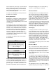
LED No.
(from left
side)
Indicated
Battery Vol-
tage Range
Approx-
imate Bat-
tery Re-
serve
L1 (red)
Below 22 V
Below 5%
L2 (yellow)
22 – 23.5 V
5%
L3 (green)
23.5 – 24 V
15%
L4 (green)
24 – 24.5 V
30%
L5 (green)
24.5 – 25 V
60%
L6 (green)
25 – 27 V
90%
L7 (green)
27 – 28 V
100%
L8 (green)
28 – 29.5 V
100%
L9 (yellow)
29.5 – 30.5 V
100%
L10 (red)
Above 30.5 V
100%
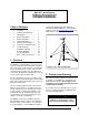
Table 1, Battery Bank Status Indications
The LED’s provide an indication of the instanta-
neous battery voltage. This voltage is affected by
the state of battery charge and the instantaneous
net current flow into or out of the battery. There-
fore, during high charging/low load periods the
gage will over-predict battery state of charge and
during low charging/high load periods the gage
will under-predict battery state of charge. Also,
the smaller the battery bank the more rapidly the
LED’s will change in response to changing wind
and electrical load conditions.
The PowerCenter is designed to work with
flooded-cell or sealed, deep-cycle, lead-acid bat-
teries. Do not use other types of batteries, such
as Ni-Cad batteries, without first contacting Ber-
gey Windpower Co.
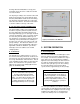
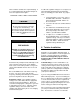
Mode Selector Button
The button on the backside of the enclosure (see
Figure 12) is used to manually select several dif-
ferent modes of operation. If the controller is in
any of these manually selected modes press and
release the button to exit the mode. To select an
optional mode (described below) the mode selec-
tor button is pressed and held until the set of 4
System Status or 10 Battery Bank Status LED’s
indicate the function you desire.
Upon first pressing the mode selector button the
Slow Mode LED (yellow) will begin to blink rapidly
and will continue for 10 seconds. Releasing the
button during this time period applies electrical
braking for Stop Mode.
If the button is held for longer than 10 seconds,
then the Battery Bank Status LED’s will begin to
blink, indicating battery bank equalization mode.
Release the switch during this 10 second period
to initiate the Equalization Function.
Continuing to hold the mode selector button will
cause the voltage indicating LED’s to stop flashing
and the Slow Mode LED (yellow) will begin to
blink slowly, indicating Manual Slow Mode. Re-
lease the switch during this 10 second period to
put the wind turbine into Slow-Mode.
If the mode select button is held still longer (total
of 30 sec) then the Battery Bank Status LED’s will
begin cycling rapidly from no LED’s ramping up to
10 LED’s and back down again, indicating the
Watt Display mode. Release the switch during
this period to select the watt display function.
If the button is not released during the watt display
mode activation then the controller will return to
normal operating mode. All LED’s will be indicat-
ing as would be expected in normal operation and
releasing the mode selector button will now have
no effect.
Using the PowerCenter Functions
(Modes)
Stopping the Turbine
The rotor can be stopped under most wind condi-
tions using the electrical braking function in the
PowerCenter. You might use this function, for
example, before lowering or climbing the tower.
We do not recommend frequent use of the braking
function because of the heat stress it puts on the
alternator, particularly when the winds are strong.
In fact, the PowerCenter software contains “road-
blocks” to repeated use of the braking function
over a short time.
To initiate stopping simply press the mode selec-
tor button and release while the Slow Mode LED
(yellow) is rapidly blinking. The turbine should
stop quickly. If it does not then the winds may be
too high to stop the turbine. As soon as there is a
lull in the winds the turbine should stop.