
Use and Care Manual

- 27 -
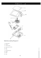
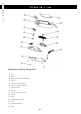
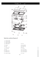
13) Fan
14) Main PCB
15) Filter PCB
16) Coil
17) Sensor
18) Control PCB
19) Control panel
20) Control panel
21) Crew
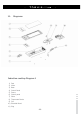
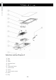
Induction cooktop Diagram 5
1) Ceramic plate
2) Ceramic plate
3) Upper housing
4) Control PCB
5) Sensor
6) Coil
7) Power cord
8) Main PCB
9) Fan
10) Rubber foot
11) Rubber foot
12) Lower housing