
HUHAA Product Manual


Horizontal Discharge (Rod-mount from Ceiling)
1. Install four threaded mounting rods in the threaded holes and
secure in place using lock nuts. (See Table 2).
2. Securely attach the four mounting rods to the ceiling. (Refer
to Table 1 for wall and ceiling clearances, and Table 2 for
m
ounting rod spacing).
Vertical Discharge (Rod-Mount from Ceiling)
1. Remove bolts from the threaded holes in the back of the
heater.
2. Install four threaded mounting rods in the threaded holes and
secure in place using lock nuts.
3. Securely attach the four mounting rods to the ceiling. (Refer
to Table 1 for wall and ceiling clearances, and Table 3 for
m
ounting rod spacing dimensions.)
TTaabbllee 33.. RRoodd TThhrreeaadd TTyyppee aanndd SSppaacciinngg DDiimmeennssiioonnss,, iinncchheess ((mmmm))
ffoorr VVeerrttiiccaall DDiisscchhaarrggee
Rod Thread
Unit Type EF GH
3 - 5 kW
69
3
/
4
24
1
/
16
5
/
16
- 18
(152.4) 247.7) (50.8) (103.1)
7.5 - 20 kW
8
7
/
8
14
5
/
8
25
1
/
8
(225.6) (371.6) (50.8) (130.3)
25 - 30 kW
3
/
8
- 16
14
1
/
2
21
1
/
4
2
3
/
1
6
6
3
/
1
6
(308.1) (539.8) (55.6) (157.2)
WIRING
Branch Circuit (Power)
1. Connect heater only to the voltage, amperage and frequency
specified on the nameplate.
2. Field wiring must be properly sized to carry the amperage in
accordance with the NEC.
3. The access door is hinged. There are either one or two
screws accessible from the bottom, that must be removed to
gain access.
4. A knockout is provided in the back of the heater close to the
power terminal block and the control terminal board. The
control terminal board knockout is 1/2 inch (12.7 mm) conduit
size. The power terminal block knockout is multiple diame-
ter. Use the diameter that fits the required conduit size.
5. A ground terminal is provided near the power terminal board.
The ground wire should be connected before other connec-
tions are made.
6. The power terminal board is equipped with box terminals
sized to accept the correct size power supply wire. Wire
rated at 600 V and 60° C is satisfactory for the heater branch
circuit. Either aluminum or copper wire is satisfactory for
connection to the heater power terminal board box terminal.
Copper wire is recommended and must be used with built-in
disconnect switch.
7. Each heater has a wiring diagram affixed to the inside of the
a
ccess door. Consult this diagram before making any field
connections.
8. Single or three-phase power connections may be used with
h
eater models HUHAA520, HUHAA524, HUHAA720,
HUHAA724, HUHAA1020, HUHAA1024 and HUHAA1520.
These units are factory wired for single phase operation. If
these heaters are for use with three-phased power, recon-
nect the wires as indicated in the wiring diagram attached to
the heater. Additional information can be found by looking at
the wiring illustrations in Figures 3a and 3b and following the
directions shown below.
On models HUHAA520, HUHAA524, HUHAA720, HUHAA724,
HUHAA1020 and HUHAA1024 (Figure 3a), move only the two
w
ires marked “A1” and marked “B1”; do not move or change any
other wiring. The element lead wire marked “B1” which is facto-
ry connected to the power terminal block (terminal located clos-
est to the elements) must be moved to terminal “B” on the three-
phase terminal block.
The relay (contactor) lead wire “A1” must be moved from the
end terminal of the power terminal block (terminal closest to the
contactor or control terminal board) to the “A” terminal of the
lower terminal block (center terminal).
Model HUHAA1520 (Figure b) has two three-phase terminal
blocks located adjacent to the relays (contactors). Move only
the two wires marked “C1” and “D1” on each of these two three-
phase terminal blocks to terminal “B”. Do not move or change
any other wires.
9. Electrical Accessories, either kits or factory-installed
options, are shown connected by a dashed line on the
heater wiring diagram.
10. 208/240 Volt Heater: The heaters are wired for 240V from
factory. When heater is to be connected to 208V supply, the
transformer leads have to be interchanged. For units rated
30/40kW or higher, interchange ORANGE and RED primary
leads. The black colored lead is the COMMON for the trans-
former (50VA) provided with the high wattage units. For
lower kW rated heaters, interchange BLACK and RED pri-
mary leads. The WHITE colored lead is the COMMON for
the control transformer provided with these heaters. Always
refer to the wiring diagram on the cover of the heater before
making this reconnection of transformer primary leads.
Control Wiring
1. Use min. 600 volts, NEC Class 1 insulated wire for all control
circuit wiring.
2. Use a crimp-on type fork terminal on the wire ends that
attach to the control terminal board if more than one connec-
tion is to be made under the terminal screw.
3. On units not provided with internal contactor
(3 & 5 KW),
refer to Figure 4 for wiring diagram.
Note: Thermostat and control circuit wiring must be suitable
to handle the full load of the heater (example HUHAA520 is
rated 24 amps)
4. On units provided with internal contactor
(units rated 7 KW
and higher) refer to Figure 5 for wiring diagram. Control
wiring must be rated minimum 18 AWG.
LINE VOLTAGE IS PRESENT ON SOME OF THE TERMI-
NALS ON THE CONTROL TERMINAL BOARD. ALWAYS
DISCONNECT THE POWER FROM THE HEATER BEFORE
MAKING ANY CONNECTIONS TO THE CONTROL BOARD
TO PREVENT ELECTRIC SHOCK HAZARD.
3
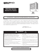
FFiigguurree 22.. VVeerrttiiccaall DDiisscchhaarrggee MMoouunnttiinngg aanndd RRoodd SSppaacciinngg
(TOP VIEW)