
Installation manual

12
REPLACEMENT PARTS
Only authorized replacement parts may be used in performing service on the appliance. Replacement parts are available
from factory authorized parts distributors.
Conversion to different types of gas
Before carrying out any maintenance work, disconnect the appliance from the gas and electric
supply. For Natural Gas fit regulator assembly described in Fig.
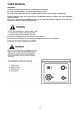
Adaptation of the pressure regulator for use with different type of gas
The pressure regulator supplied with the appliance is a convertible type pressure regulator for use with Natural Gas at a
nominal outlet pressure of 4” w.c. or LP gas at a nominal outlet pressure of 11” w.c. and it is pre-arranged from the
factory to operate with one of these gas/pressure as indicated in the labels affixed on the appliance, package and
Instruction booklet.
To convert the regulator for use with other types of gas follow these instructions:
1) Unscrew by hand the upper metal stopper of the regulator.
2) Unscrew by hand the white plastic piece screwed under the above mentioned metal stopper, afterward screw it again
in opposite way under the metal stopper (for gas reference see the written “LP” and “NAT” with relative indicating arrows
on the white piece).
3) Screw again by hand the metal stopper in the original position on the regulator.
Following these exact instructions the gas regulator is converted for use with the other gas/pressure.
It is essential that the gasket and the pressure test point stopper are properly installed to avoid gas leakage
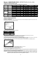
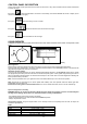
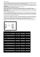
- CHANGING THE NOZZLES FOR USE WITH OTHER TYPES OF GAS:
To change the nozzles of the burners use the following procedure:
Lift up the burners and unscrew the nozzles ( Fig.) using an adjustable spanner of 7 mm and change the nozzles with
those designed for the new gas supply according to the information given in TABLE shown below.
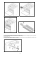
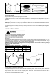
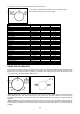
Follow the instructions below to change the oven burner nozzle:
1) Remove the oven door (Fig. 9A-9B)
2) Remove the lower frontal cavity gasket and the enamelled cavity base plate (Fig. 10)
3) Loosen and the screw V and pull out the burner from the support being careful not to damage the ignition plug and
the thermocouple (Fig. 11)
4) Unscrew the nozzle R (Fig. 11) using a 7 mm. spanner and replace it with the nozzle for the new type of gas
according to what is indicate in the table below
5) Re-install all the parts in revers sequence from 3 to 1