
manual


3
IMPORTANT INFORMATION FOR INSTALLING THE APPLIANCE
The cooker can be installed separately, as a freestanding unit, or between kitchen units or between a kitchen
unit and the wall. The device must be installed in accordance with the regulations stated in UNI 7129 and UNI
7131 standards.
This appliance is not connected to devices which exhaust combustion products.
Special attention must be focused on the prescriptions described below regarding room aeration and
ventilation. Any hanging cabinets installed above the work surface must be located at a distance of no less than
700 mm.
ROOM VENTILATION
To ensure that the appliance operate correctly, the room where it is installed must be continuously ventilated. The room
volume should not be less than 25 m³ and the quantity of air needed shall be based on the regular combustion of gas and
on the ventilation of the room. Natural air will flow through permanent openings in the walls of the room to be ventilated:
these openings will be connected with the outside environment and shall have a minimum cross-section defined by the
current national standards regarding room ventilation (see Fig. 3).
These openings shall be built so that they cannot be clogged.
Indirect ventilation is also permitted by taking air from the rooms adjacent to the one to be ventilated.
LOCATION AND AERATION
The gas cooking appliances must always evacuate the combustion products by means of hoods connected to chimneys,
flues or directly outside (see Fig. 4). If a hood cannot be installed, it is possible to use a fan installed on a window or
directly facing outdoors, to be operated together with the appliance (see Fig. 5), provided that there is strict compliance
with the ventilation regulations.
HEIGHT-ADJUSTABLE FEET (figure.6)
The feet are packed in the top box.
The feet should be installed with the cooker close to its final installation position; the feet are not safe to move the cooker
long distances.
After unpacking the cooker, lift it with your foot, to fit the cooker feet in the bases at the bottom. Slowly lower the cooker
so its weight is resting on the feet and on the assembly fixings. We recommend using a lifting device or pallet instead of
tilting the cooker.
INSTALLING THE TOEKICK PANEL (only available for some models)
After installing the feet, install the cooker skirt as shown in the pictures in Figure 7
INSTALLING THE RISER
Remove the 2 screws securing the hob at the rear, as shown in (figure 8)
Put the upstand in place and secure at the bottom with the two screws, as shown in (figure 8)
Secure the middle of the upstand using the screws provided with the upstand (figure 8)
INSTALLING THE HOB RAIL AND OVEN HANDLE
The rail and handle are packed with the upstand.
The rail is only available on some models.
Assemble the hob rail and oven handle as shown in the pictures
(fig.9A –9B –9C)
INSTALLING THE SYSTEM TO PREVENT OVERTURNING
To prevent the appliance from accidentally overturning, the system provided must be installed. Install the system as
shown in the fig.10.
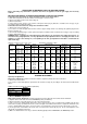
APPLIANCE GAS CONNECTION
Before connecting the appliance to the gas network, make sure that the data on the label attached to the food
warmer drawer or on the back of the cooker are compatible with what is indicated for the gas distribution
network.
A label attached to the last page of this handbook and in the food warmer drawer (or on the back) of the
appliance indicates the appliance adjustment conditions: type of gas and operating pressure.
IMPORTANT: This appliance must be installed in compliance with current national standards in force and used
only in a well-ventilated room.
WARNING: It should be recalled that the appliance utilises a threaded 1/2" gas cylindrical male fitting according
to UNI-ISO 228-1.
To connect the appliance to the gas network with a flexible rubber hose, a supplemental hose nipple fitting is
needed (see Fig. 11) which is supplied with the appliance.