INSTALLATION, MAINTENANCE AND USE INSTRUCTIONS FOR FREE-STANDING COOKERS MAS HER PRO READ THE INSTRUCTION BOOKLET BEFORE INSTALLING AND USING THE APPLIANCE. The manufacturer will not be responsible for any damage to property or to persons caused by incorrect installation or improper use of the appliance. The manufacturer is not responsible for any inaccuracies, due to printing or transcription errors, contained in this booklet. In addition, the appearance of the figures reported is also purely indicative.
CONTENTS: INSTALLER TECHNICAL MANUAL…………………………………………………………………….. pg.2 APPLIANCE MAINTENANCE ....................................................................................................... pg.4 INSTALLING RANGE COOKER .................................................................................................... pg.5 BURNER ADJUSTMENT ONLY MODEL 60X60 .......................................................................... pg.8 GAS HOB……………………………………………………………………………………………………pg.11 THE CHEF TOP ..
Installer information The installation, all adjustments, transformations and maintenance listed in this part of the manual must be carried out only by skilled personnel. Improper installation may cause damage to persons, animals or property, for which the manufacture will not be held responsible. The appliance safety or automatic adjustment devices may be changed during the service life of the system only by the manufacturer or by the duly authorised supplier.
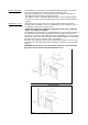
APPLIANCE MAINTENANCE ATTENTION: IMPORTANT WARNINGS For cookers resting on a base ATTENTION: If the cooker rests on a base, take the measures necessary to prevent the cooker from sliding along the support base. For cookers with electric ovens The unit becomes hot during use. Do not touch the heating elements inside the oven. For cookers with electric ovens ATTENTION: The accessible parts can become hot during use. Keep children away from the appliance.
considered when undertaking any installation. Failure to install the appliance correctly will render the warranty null and void. Range cookers are heavy and should be handled by two people. Never lift or drag a range by the oven handles as damage may occur. Note: Pictures and graphics in this manual cover different models and may vary in minor details from your cooker.
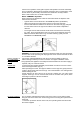
less. If the cooker is installed in a room with a volume of less than 5m³, then a vent with an effective area of 100cm³ is required. If it is installed in a room with a volume of between 5m³ and 10m³, then an air vent with an effective area 50cm³ is necessary. If there are other fuel burning appliances in the room, please consult national standards for guidance.
ATTENTION: The appliance conforms with the regulations of directives 90/396EEC (Gas Directive) regarding gas appliances for domestic use and the like, 73/23 (Low Voltage Directive) regarding electrical safety and 2004/108/CE, (EMC Directive) regarding electromagnetic compatibility. Ensure that the electricity supply is switched off before making the connection. This appliance must be earthed.
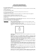
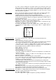
- Unscrew the nozzle R (Fig.8) using a 10 mm span ner and replace it with th e nozzle needed for the new type of gas according. Fig 7 Fig 8 OVEN BURNER ADJUSTMENT ONLY MODEL 60X60 Only model 60x60 1)Primary air adjustment: Oven burner adjustment: follow the instructions below to adjust the primary air for the over burner: 1) Remove the oven bottom. 2) Loosen the screw P and adjust the position X of the Ve nturi cone (Fig.9) according to the measurements.
Check correct operation of the ignition system and operation of burners individually and in combination. Burner flames should be clear blue, with no yellow tipping. If the burners show any abnormality check that burner heads are correctly located. Note: These burners have no aeration adjustment. Burner "MINIMUM" adjustment: Work surface burner adjustment: follow the instructions below to adjust the work surface burner minimum: - Light the burner and set the knob to the MINIMUM position (small flame).
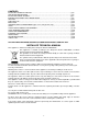
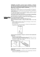
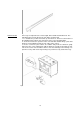
Fig 12 Anti-tilt restraint Once legs are adjusted to the correct height, fit the anti-tilt restraint brackets. The anti-tilt brackets must be fixed to the rear wall as shown below. 1. To calculate the position of brackets up from the floor, measure to the bottom of the anti-tilt bracket location slots on the back of the cooker and add 32mm. 2. Secure the brackets in position on the rear wall with suitable fixings. (Note that brackets are fixed 60mm in from the side edges of the cooker). 3.
GAS HOB Using the gas hob As the following points: - To light a burner, press in the control knob (Fig.14A-14B) and turn it anticlockwise, to the large flame position. - Continue to hold the knob In until the burner lights. Adjust the flame as required, continue to hold the knob in far 5 to 10 seconds before releasing - The Chef Top (optional) is powered by the gas burners. - See page 7 for usage instructions.
THE CHEF TOP Using the Chef Top The Chef Top is manufactured from 5mm thick stainless steel designed for a high heat retention across the plate. The very high cooking temperature makes the Chef Top ideal for searing meats and vegetables and for oriental style recipes.
3 Pour 1 tsp vegetable oil into the centre 01 the griddle. Rub the oil aver the entire surface of the griddle using a heavy cloth. 4 Turn the control knob to a maximum setting. Turn the heat off when the oil begins to smoke. Allow the griddle to cool. 5 Repeat step 3. Be sure to cover the entire surface with the oil. 6 Repeat step 4. Allow the griddle to cool. Wipe the entire surface of the griddle using a heavy cloth. Apply a very thin layer of vegetable oil. The griddle is now ready to use.
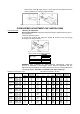
INDUCTION 60x60 model Fig 17A 90x60 or 100x60 model Fig 17B Functions : Keep Warm 42°C : Keep Warm 70°C 1…9 : Power Level P : Booster A : Heating Accelerator Hob control knob These knobs provide control of the ceramic hob's cooking zones. The zone it controls is shown above each knob. Turn the knob to the right to set the zone's operating power; the settings range from a minimum of 1 to a maximum of 9. The working power is shown by a display on the hob.
(60X60model only) same features as a single cooking zone. Booster function isn’t allowed. 1 – rotate both knobs, rear right and front right, at the same time in the P position and keep the knobs in that position. 2 – we see that the ∏ symbol blinks in the display, then after a few seconds the ∏ symbol appears on the rear right display and the front right display shows the power level. 3 – to control the bridge power level use the knob 4 (front right zone).
necessary for the heating process. Vessels made from the following materials are not suitable: glass; porcelain; pottery; steel, aluminium or copper without magnetic bottom; To check that a pan is suitable, simply place a magnet close to its bottom: if the magnet is attracted, the pan is suitable for induction cooking. If no magnet is to hand, put a little water in the pan, place it on a cooking zone and switch it on. If the symbol appears on the display instead of the power, the pan is not suitable.
Attention: Take care not to spill sugar or sweet mixtures onto the hob during cooking, or to piace materials or substances which might melt (plastic or aluminium foil) on it; if this should occur, to avoid damage to the surface, tum the heating off immediately and clean with the scraper supplied while the cooking zone is stili warm. If the ceramic hob is not cleaned immediately, residues may form which cannot be removed once the hob has cooled.
Fig 20A Fig 20B Most foods such as bread products and bacon are grilled on the higher settings For thicker cuts of meat, chicken pieces etc. you should use fan assisted grilling in the main oven. See page 24.
operation. As for cookers without ignition trough knob, press the thermostat knob and the key with the spark symbol, wait about 10 seconds after the burner has been completely lit and then release the knob. Make sure that the burner remains on, otherwise repeat the operation. The ignition device should not be used for more than 15 seconds.
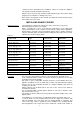
PASTRY FRUIT PIE TEA CAKE BRIOCHES SPONGE CAKE RING CAKE SWEET PUFF PASTRIES RAISIN LOAF STRUDEL SAVOIA COOKIES APPLE FRITTERS SAZOIARDI SANDWICH TOAST SANDWICH BREAD PIZZA 220 190 175 235 190 220 220 180 190 220 220 250 220 220 (210) (180) (165) (225) (180) (210) (210) (170) (180) (210) (210) (240) (210) (210) 2 2 2 2 2 2 2 2 2 2 2 3 2 2 35-40 50-55 25-30 20 30-40 20 15-20 15-20 15 20 20-30 5 30 20 Using the 2 + 0 switch – the symbol indicates that the electric fan, and the oven light have been turned
the two knobs, no effect will result on oven operation except only for lamp or fan when switched on. Electric oven is heated by two resistances: one upper resistance and one circular resistance; by turning the switch knob (Fig.26A-26B) the resistance referred to the symbol printed on the knob ring will be switched on but in order to put it in operation the thermostat knob has to be turned until the orange light on will confirm that resistance is in operation.
on and off during cooking as the elements maintain the temperature (The operation of the oven is indicated by the display of the programmer for PRO T version only). 3 To turn the oven off, turn the function selector and temperature knobs anticlockwise back to •. Steam may be generated when cooking. As a precaution, always open the door in two stages. First, partially open the door by 100mm for a few seconds to allow the steam to escape, then open the door fully.
When using the Fan Assisted or True Fan oven function, it is advisable to reduce the oven temperature by 20°C if following a recipe written for a conventional oven. Check the food often through the latter stages of cooking until you are used to the cooking times and temperatures. The ovens have a range of cooking functions providing different heat zones. The 'True Fan' function for instance, is most suitable for cakes, desserts and batch baking.
Using the grill The grill pan consists of a wire trivet and enamel tray. Place food on the wire trivet. A lower shelf position can be used to slow cooking down, or the temperature can be reduced. A detachable grill pan handle is supplied for removing the hot tray. Both the Fan Assisted Grill and Conventional Grill functions are designed to be used with the oven door closed. This ensures efficient preheating and even cooking.
fork should enter just below the thighs. Tighten the thumbscrew into place. Ensure that the food is well balanced to avoid stress on the motor drive. The maximum weight bearing of the spit is 3.5kg. 7 Turn off the oven. Fit the handle to the spit assembly, then place the spit over the wire support shelf and place the spit end into the hole In the rear oven wall. Locate the spit support onto the wire shelf. Remove the handle (the handle is used solely for moving the spit) and close the oven door.
Home screen - To active timer/set up menu touch control zones. In this screen the temperature knob is not active. To switch directly to the functions cooking selection screen turn the function knob and the icon of the selected function will appear on the display. Timer/set up menù To advance to the system settings select the set-up icon. In this screen it is possible to set the time (12 or 24h), the type of degrees (metric °C or imperial °F) and the intensity of the buzzer.
Choose the desired temperature turning thermostat knob to move to the cooking tools menu. Wait to 3/4 seconds confirm the selected value and the display will show the status screen. Status screen Cooking tools menu If not selected any cooking instrument after inactivity of 3/5 seconds the screen returns to the initial state or to status screen in case the oven is in operation.
screen and select delay touching the corresponding touch control zone. Set desired time before oven will turn on and confirm The oven will turn on at the set time and it will be confirmed with a repeating tone. Touch any touch control area to stop tone. Leave menù . After 3/5 seconds of inactivity the screen returns to the status screen. Cooking time Press the touch zone next to (settings menu) to enter the cooking tools menu screen and select cooking time touching the corresponding touch control zone.
Set the desired food temperature with and confirm . The display will show the set temperature and the actual temperature measured by the probe. The oven will turn off when the desired food temperature is reached. End of cooking will be confirmed with a tone. To stop tone touch any touch control area. Leave menù . After 3/5 seconds of inactivity the screen returns to the status screen. The probe works by measuring the temperature inside a joint of meat.
temperatures below. It is not recommended to cook poultry using the probe. Cut of meat Topside of beef Topside of beef Deboned leg of lamb Deboned leg of pork Preferred result Medium rare Medium Medium pink Cooked through not pink Suggested core temp 63°C 70°C 69°C 85°C minimum temp - The meat does not need to rest before carving as it is cooked at a lower temperature than roasting. Important DO NOT LEAVE THE PROBE IN THE OVEN CAVITY WHEN NOT IN USE.
VENTILATED ELECTRIC OVEN COOKING TABLE TEMP °C HEIGHT MINUTES MEAT PORK ROAST BEEF ROAST (YOUNG STEER) BEEF ROAST VEAL ROAST LAMB ROAST ROAST BEEF ROAST HARE ROAST RABBIT ROAST TURKEY ROAST GOOSE ROAST DUCK ROAST CHICKEN 160-170 170-180 170-190 160-180 140-160 180-190 170-180 160-170 160-170 160-180 170-180 180 2 2 2 2 2 2 2 3 3 3 2 2 70-100 65-90 40-60 65-90 100-130 40-45 30-50 80-100 160-240 120-160 100-160 70-90 FISH 160-180 2-3 PASTRY FRUIT PIE TEA CAKE BRIOCHES SPONGE CAKE RING CAKE SWEET PUF
When the oven is turned off, the temperature on the thermometer will slowly drop until it reaches room temperature. Note: The Thermostat Position and Oven Temperature correspondence in table no. 6 is indicative and depends on various factors such as the type of gas and supply pressure. Follow the thermometer temperature for cooking.
When re-assembling the burners, always ensure that the notches on the burner ring are seated firmly into the base far the gas to ignite and the flame to be stable. (See burner assembly instructions Assembly of the burners (Fig.32) The circular burners have two notches, which fit around the thermocouple and the ignition candle (on the dual wok burner these notches are located on the inner ring). Once the burner is securely in place, the black burner cap(s) should sit on top.
Fascia, controls and external surfaces Do not use strong or abrasive cleaning agents or materials on the controls. fascia panel or coloured cooker surfaces This can cause damage to the calibrations and icons and permanently scratch the surfaces. Coloured surfaces: Clean with a sott cloth, warm water and washing-up liquid Whilst still damp, polish dry with an microfibre cloth. Stainless steel: Far stubborn marks use a reputable non-abrasive stainless steel cleaner.
border is nearest the cooker. It is not necessary to remove the door in order to clean the glass panes. Oven interior To tell whether your oven has stay clean liners look at the oven walls. If the surface is grey in colour and rough in texture then this is a stay clean liner. If the surface is smooth and black, this is an enamelled surface. Fitting the stay clean liners If you have purchased stay clean liners as an accessory, they are easy to fit.
The side shelf runners and shelves can be cleaned In a dishwasher. This is not advisable with the telescopic runners as the detergent may remove the lubrication on the runners. Removing and refitting the telescopic runners - The telescopic runners fit any shelf level, and work with both the grill tray and wire shelves. - Locate the two spring clips at the front and back of the runners. - Gently pull down the front spring clip. - Pull the runner away from the oven side - be careful not to strain the clip.
ACCESSORIE Plinth kits The three-sided plinth can be screwed to the underside of your cooker to conceal the adjustable legs. The plinth is 9,3cm in height (cannot be used with extra high legs, and is not suitable for 100X60 triple oven). Griddle Half flat, half ribbed griddle is perfect for searing meat, chicken and fish. Rests on pan supports of all cookers. Stay clean liners These liners are easily fitted into the back and sides of all ovens (sides only in 30cm and 40cm ovens).
TROUBLESHOOTING The oven will not operate - Is there power to the cooker? - Is he automatic programmer set to manual? - The main oven will not operate manually if the programmer is set to automatic mode. (See page 26) - Confirm that power is on by checking that the clock is functioning - Check the switch fuse or circuit breaker.
- Check that you have selected the grill function and not the top element. See pages 23-24. The main oven takes a long time to preheat - Have you tried using the Quickstart function? - Pre-heat with the Quickstart function until the temperature has been reached, then switch to your required cooking function. - Quickstart should not be operated for more than 10 minutes. - To order spare parts or accessories, please call our service & spares department.
USEFUL TIPS Cookshop thermometers - These are often slow to react and they should only be used as a guide. You should also keep in mind that oven temperatures can fluctuate between 10% and 15% during any cooking period. This is normal on any oven and is caused by the elements 'cycling' on and off. Correct cooking time In most cases, the cooking times stated in recipes should be used. However, the cooking period should be reduced for dishes that require very long cooking time (such as rich fruit cakes).