BERTAZZONI INSTALLATION AND USER MANUAL ISLAND T-SHAPE DESIGN HOODS EN BERTAZZONI INSTRUCTIONS D’INSTALLATION ET D’UTILISATION HOTTE D'INSTALLATION EN ÎLOT FR KTI..XT WWW.BERTAZZONI.
CONTENTS Section Page IMPORTANT SAFETY INSTRUCTIONS 3 RANGE HOOD DIMENSIONS 6 INSTALLATION HEIGHT REQUIREMENTS 7 PARTS 8 TOOLS NEEDED 10 VENTING METHOD 11 COMPONENTS FOR INSTALLATION TO THE CEILING 12 INSTALLING 12 OPERATING THE CONTROLS 24 CLEANING STAINLESS STEEL 26 CARING FOR FILTERS 26 REPLACING ACTIVATED CHARCOAL FILTER 27 REPLACING BULBS 27 WIRING DIAGRAM 28 WARRANTY 29 2
IMPORTANT SAFETY INSTRUCTIONS READ AND SAVE THESE INSTRUCTIONS BEFORE YOU START INSTALLING THIS Range Hood WARNING: - TO REDUCE THE RISK OF A RANGE TOP GREASE FIRE: a) Never leave surface units unattended at high settings. Boilovers cause smoking and greasy spillovers that may ignite. Heat oils slowly on low or medium setting. b) Always turn hood ON when cooking at high heat or when flambeing food (i.e. Crepes Suzette, Cherries Jubilee, Peppercorn Beef Flambé). c) Clean ventilating fans frequently.
ALL WALL AND FLOOR OPENINGS WHERE THE Range Hood IS INSTALLED MUST BE SEALED. This Range Hood requires at least 24" of clearance between the bottom of the Range Hood and the cooking surface or countertop. This hood has been approved by UL at this distance from the cooktop. This minimum clearance may be higher depending on local building codes. For gas cooktops and combination ranges, a minimum of 30" is recommended and may be required.
ELECTRICAL REQUIREMENTS A 120 volt, 60 Hz AC-only electrical supply is required on a separate 15 amp fused circuit. A time-delay fuse or circuit breaker is recommended. The fuse must be sized per local codes in accordance with the electrical rating of this unit as specified on the serial/rating plate located inside the unit near the field wiring compartment. ! WARNING • Electrical ground is required on this Range Hood.
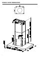
RANGE HOOD DIMENSIONS 6 0LQ ´ 0LQ ´ 0D[ ´ 0D[ ´
INSTALLATION HEIGHT REQUIREMENTS Min. 24" Min. 30" MIN. 24" OVER ELECTRIC MIN.
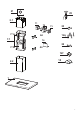
PARTS PARTS INCLUDED REF. QTY 1 Hood body 1 2 Telescopic Chimney comprising: 1 2.1 Upper Section 1 2.2 Lower Section 1 7.1 Telescopic frame complete with extractor, consisting of: 1 7.1a Upper frame 1 7.
Y1Y1 2x L 4x 2x (M4x15) (M4x15) I 4x (6x70) 21 L T1 4x I KK 4x 4x T2 (M6x80) (M6x80) T3 4x (6x70) Y1 2x 15) 2.1 T1 A A 4xT2 7.1a K 4x x80) 4x x9,5) A2 7.1b 2x x6,5) 2.2 BB 8x 8x (6,4x16x1) (6,4x16x1) A3 2x 9,5) B 12q 22 A3A3 2x 2x (2,9x9,5) (2,9x9,5) T4 A2A2 2x 2x (2,9x6,5) (2,9x6,5) T4 7.
PARTS (cont.) PARTS NEEDED PART 6" Round Metal Ductwork Drywall plugs or other suitable wall fasteners based on your installation.
VENTING METHOD 1 Ducted Venting Installation 6" Non ducted - recirculation Requires purchase of Activated Charcoal Accessory kit.
COMPONENTS FOR INSTALLATION TO THE CEILING These fasteners may need to be purchased separately depending on your installation. K 3/16 ” 3/16 ” 3/16 ” OK! T OK! OK! INSTALLING 1 12 Do not make any cutouts until you have decided whether this installation will be ducted or non-duct and then plan accordingly.
2 Put a thick, protective covering over cooktop, set-in range or countertop to protect from damage or dirt. Determine and clearly mark with a pencil on the ceiling where the rangehood will be installed. A template 21 for mounting the support is supplied in the carton with the support. Use this template to mark holes for support on the ceiling. Determine and make necessary cuts for the ductwork. The duct opening is shown on the mounting template. Install ductwork before mounting the hood.
L 4x I 3 Chimney Flues Must Be 4x Removed Before (6x70) L Installing the Hood Loosen the two screws fastening 4x the lower chimney and remove this from the lower T1frame.
4 If you need to adjust the height of the frame, proceed as follows: • Unfasten the metric screws joining the two columns, located at the sides of the frame (1,2,3,4,5,6). • Adjust the frame to the height required, then refit all the screws removed as above. 14. REMOVING THE MIDDLE TRESTLE COMPONENT NOTE: The chimney structure can reduce down to a 27 " minimum height. To reduce the height, the middle section of the support structure needs to be removed.
5 Upper Flue Must Be In Place Before Proceeding After the regulation for height adjustment, insert the upper chimney stack from above, and leave it running free on the frame. 6 Only for Ducted Venting Installation Install the Flaps included 10 with the Hood before connecting to the ductwork.
7 Now take either your wood screws or bolts depending on your set-up and screw all four into the pilot holes and leave 1/4" of the heads exposed. Next install a UL or CSA listed strain relief in the wiring box so that the screws can be tightened after the chimney support is attached to the ceiling. Now lift the chimney support into it's final position and feed the electrical supply through the strain relief.
Installation of wiring connection Remove the cover from the field wiring compartment. DO NOT turn on the power until installation is complete! Connect the Power Supply Cable to the rangehood. Connect the Green (Green and Yellow) ground wire under the Green grounding screw. Attach the White lead of the power supply to the White lead of the rangehood with a twist-on type wire connector. Attach the Black lead of the power supply to the Black lead of the rangehood with a twist-on type wire connector.
I 4x I (6x70) 4x x70) 9 L 4x Position the upper chimney section and fix the upper part to the frame using the 2 screws removed previously. T1 T2 T3 T1 T4 L 4x L I 4x I 4x 70) 10 4x Similarly, position the(6x70) lower chimney section and fix the lower part to the frame using the 2 screws removed previously.
Only for non ducted recirculating installations 11 Insert the Connector extensions T1 and T3 into the side of the Connector T2. Insert the Connector T2 into the Support bracket T4 and fix it with the screws. T1 T2 1 T3 A2 T4 2x 2 Fasten the Support bracket T4 fixing it to the upper part with the Screws.
Make sure that the Connector extensions outlet T1 and T3 is in correspondence with the Chimney openings both horizontally and vertically. Attach a charcoal filter in the correct position and block it by the fixing hooks as $ [ $ [ shown. Unlock the fixing hooks (towards the back of the hood) to remove.
Attachment of Hood Canopy 12 Remove the grease filters from the hood canopy. Remove any activated charcoal filters. Working from below, fix the hood canopy to the frame where indicated, using the 4 screws 12f, then tighten all the screws securely.
13 Connect the connector "B". Check the connection of connector "A". A 14 B Reinstall the grease filters from the hood canopy.
OPERATING THE CONTROLS FOR BEST RESULTS T1 T2 T3 T4 L Start the Range Hood several minutes before cooking to develop proper airflow. Allow the Range Hood to operate for several minutes after cooking is complete to clear all smoke and odors from the kitchen. T1 1 Button T2 2 T3 3 T4 4 L T1 T2 T2 T3 T3 T4 T4 L T3 T4 T4 L L L Function Fan off button:turn the blower Off. The fan can be operated by pressing any of the fan setting buttons.
Remote control information The appliance can be controlled using a remote control powered by a 1.5 V carbon-zinc alkaline batteries of the standard LR03-AAA type (not included). REMOTE • Used batteries must CONTROL be disposed of in the proper manner.
CLEANING STAINLESS STEEL Cleaning Exterior surfaces: Please note, abrasives and scouring agents can scratch range hood finishes and should not be used to clean finished surfaces. Stainless Steel finish cleaning instructions: Clean exterior surfaces with a commercially available stainless steel cleaner. Use a soft microfiber cloth and to wipe going with the grain of the stainless steel.
REPLACING ACTIVATED CHARCOAL FILTER The filter is not washable and cannot be regenerated, and must be replaced approximately every 4 months of operation, or more frequently for particularly heavy usage. • Remove the Filters one at a time, pushing them towards the back of the unit and at the same time pulling downward. • Remove the saturated charcoal filter by releasing the hooks. • Fit the new filter and fasten it in its correct position. • Replace, taking care to ensure that the handle faces forwards.
WIRING DIAGRAM 28
WARRANTY 25 Please kindly register on our web site www.bertazzoni.com to validate your new product warranty and help us to assist you better in case of any inconvenience. TWO YEAR LIMITED WARRANTY The warranties provided by BertazzoniSpa in this statement apply exclusivelyto Bertazzoni appliances and accessories sold as new products to the original owner by a Bertazzoni authorized distributor, retailer, dealer or service center and installed in the United States and Canada.
TABLE DES MATIÈRES Section Page CONSIGNES DE SÉCURITÉ IMPORTANTES 31 DIMENSIONS DE LA HOTTE 34 EXIGENCE D’INSTALLATION EN HAUTEUR 35 PIÈCES 36 OUTILS NÉCESSAIRES 38 MÉTHODE D'AÉRATION 39 COMPOSANTS POUR L'INSTALLATION AU PLAFOND 40 INSTALLATION 40 FONCTIONNEMENT DES COMMANDES 52 NETTOYAGE DE L'ACIER INOXYDABLE 54 ENTRETIEN DES FILTRES 54 REPLACEMENT FILTRE À CHARBONS ACTIFS 55 REMPLACEMENT DES AMPOULES 55 SCHÉMA DE CÂBLAGE 56 GARANTIE 57 30
CONSIGNES DE SÉCURITÉ IMPORTANTES LISEZ ET SAUVEGARDEZ CES INSTRUCTIONS AVANT DE COMMENCER L'INSTALLATION DE CETTE Hotte de cuisine AVERTISSEMENT : - AFIN DE RÉDUIRE LE RISQUE D'UN INCENDIE DE GRAISSE SUR LA CUISINIÈRE : a) Ne laissez jamais les appareils de surface sans surveillance si les paramètres de réglage sont élevés. Les débordements causent des fumées et des projections de graisse susceptibles de prendre feu. Chauffez l’huile lentement à des valeurs basses à moyennes.
2. 3. 4. Une quantité suffisante d'air est nécessaire pour assurer la bonne combustion et l'évacuation des gaz par le conduit de fumée (cheminée) de l’équipement à combustible, afin d'éviter tout refoulement. Suivez les directives du fabricant de l'équipement de chauffage et les normes de sécurité telles que celles publiées par la National Fire Protection Association (NFPA) et l'American Society for Heating, Refrigeration and Air Conditioning Engineers (ASHRAE), ainsi que les codes locaux.
Installations par temps froid Un registre anti-refoulement supplémentaire de contre-tirage doit être installé pour minimiser le retour de l'air froid et une coupure thermique non métallique doit être installée pour minimiser la conduction des températures extérieures dans le système de ventilation. Le registre doit se trouver du côté de l'air froid de la rupture thermique.
DIMENSION DE LA HOTTE 34 0LQ ´ 0LQ ´ 0D[ ´ 0D[ ´
EXIGENCE D’INSTALLATION EN HAUTEUR Min. 24 po Min. 30 po MIN. 24 PO SUR ÉLECTROMÉNAGER ÉLECTRIQUE MIN.
PIÈCES PIÈCES INCLUSES RÉF. QTÉ 1 Corps de la hotte 1 2 Cheminée télescopique qui comprend : 1 2.1 Section supérieure 1 2.2 Section inférieure 1 7.1 Châssis télescopique avec extracteur, composé de : 1 7.1a Châssis supérieur 1 7.1b Châssis inférieur 1 10 Volets 2 25 Télécommande 1 Extension connecteur de sortie air 2 T2 Connecteur de sortie d'air 1 T4 Support de fixation du connecteur de sortie d'air 1 T1-T3 36 PIÈCE RÉF.
Y1Y1 2x L 4x 2x (M4x15) (M4x15) I 4x (6x70) 21 L T1 4x I KK 4x 4x T2 (M6x80) (M6x80) T3 4x (6x70) Y1 2x 15) 2.1 T1 A A 4xT2 7.1a K 4x x80) 4x x9,5) A2 7.1b 2x x6,5) 2.2 BB 8x 8x (6,4x16x1) (6,4x16x1) A3 2x 9,5) B 12q 22 A3A3 2x 2x (2,9x9,5) (2,9x9,5) T4 A2A2 2x 2x (2,9x6,5) (2,9x6,5) T4 7.
PIÈCES (suite) PIÈCES NÉCESSAIRES PIÈCE Conduit métallique rond de 6 po Chevilles pour placoplâtres ou autres fixations murales appropriées en fonction de votre installation. ACCESSOIRES DISPONIBLES ACCESSOIRES SKU# Replacement filtre à charbons actifs # 901497 Kit de filtre à chicane # 901581 Installation du kit de couverture du conduit jusqu'à 10'.
MÉTHODE D'AÉRATION 1 Installation de la ventilation par conduits 6" Sans conduit - recirculation Nécessite l'achat du kit d'accessoires pour charbon actif.
COMPOSANTS POUR L'INSTALLATION AU PLAFOND Ces éléments de fixation peuvent devoir être achetés séparément en fonction de votre installation. K 3/16 ” 3/16 ” 3/16 ” OK! T OK! OK! INSTALLATION 1 40 Ne faites aucune découpe avant d'avoir décidé si l'installation se fera avec ou sans conduit et planifiez en conséquence.
2 Recouvrez d'une bâche épaisse et couvrante la table de cuisson, la cuisinière encastrée ou le comptoir pour les protéger des dommages et de la saleté. Déterminez et marquez clairement au crayon sur le plafond l'endroit où la hotte sera installée. Vous trouverez un gabarit 21 pour le montage du support dans le carton avec le support. Utilisez ce gabarit pour marquer les trous du support au plafond. Repérez les positions et faites les découpes nécessaires pour le conduit.
L 4x I 3 Les conduits de cheminée 4x doivent être (6x70) L retirés avant l'installation de la hotte. Desserrez les deux vis qui fixent inférieur. 4x la cheminée inférieure et retirez-la du châssisT1 I 4x (6x70) Y1 T2 2x (M4x15) T1 Y1 T2 T3 K 2x (M4x15) 4x (M6x80) K T4 A 4x (M6x80) T4 4x (3,5x9,5) L 4x A 4x (3,5x9,5) A2 Desserrez les deux supérieur.
4 Si vous devez régler la hauteur du châssis, procédez comme suit : • Dévissez les vis métriques qui relient les deux colonnes, situées sur les côtés du châssis (1,2,3,4,5,6). • Réglez le châssis à la hauteur souhaitée, puis remettez en place toutes les vis retirées comme indiqué ci-dessus. 14. REMOVING THE MIDDLE TRESTLE COMPONENT NOTE: The chimney structure can reduce down to a 27 " minimum height. To reduce the height, the middle section of the support structure needs to be removed.
5 Le conduit supérieur doit être en place avant de commencer. Après le réglage de la hauteur, insérez la cheminée supérieure et faites-la glisser sur le châssis. 6 Seulement pour l'installation d'un conduit d'évacuation Installez les rabats inclus 10 avec la hotte avant de la raccorder au conduit.
7 Prenez maintenant vos vis à bois ou vos boulons, selon votre installation, et vissez les quatre dans les trous pilotes en laissant 1/4 po de la tête exposée. Installez ensuite une décharge de traction homologuée UL ou CSA dans la boîte de câblage afin de pouvoir serrer les vis après avoir fixé le support de cheminée au plafond. Soulevez maintenant le support de cheminée dans sa position finale et faites passer l'alimentation électrique par la décharge de traction.
Installation de la connexion de câblage Retirez le couvercle du compartiment de câblage de terrain. NE mettez PAS l'appareil sous tension tant que l'installation n'est pas terminée ! Connectez le câble d'alimentation électrique à la hotte. Connectez le fil de terre vert (vert et jaune) sous la vis de mise à la terre verte. Attachez le fil blanc de l'alimentation au fil blanc de la hotte avec un capuchon de connexion.
I 4x I (6x70) 4x x70) 9 L 4x Positionnez la section supérieure de la cheminée et fixez la partie supérieure au cadre à l'aide des 2 vis retirées précédemment. T1 T2 T3 T1 T4 L 4x L I 4x I 4x 70) 10 4x (6x70) De même, positionner la partie inférieure de la cheminée et la fixer au châssis à l'aide des deux vis retirées précédemment.
Uniquement pour les installations de recirculation sans conduit 11 Insérez les extensions T1 et T3 du connecteur dans le côté du connecteur T2. Insérez le connecteur T2 dans le support T4 et fixez-le avec les vis. T1 T2 1 A2 T4 2x 2 Fixez le support T4 en le fixant à la partie supérieure avec les vis.
Assurez-vous que les extensions des connecteurs T1 et T3 correspondent aux ouvertures de la cheminée, aussi bien horizontalement que verticalement. Fixez un filtre à charbon à la position adéquate et bloquez-le par les crochets de $ [ $ [ fixation comme indiqué. Déverrouillez les crochets de fixation (vers l'arrière de la hotte) pour les retirer.
Fixation de l'auvent de la hotte 12 Retirez les filtres à graisse de l'auvent de la hotte. Retirez tous les filtres à charbon actif. En travaillant par le bas, fixez l'auvent de la hotte au cadre aux endroits indiqués, à l'aide des 4 vis 12f, puis serrez toutes les vis fermement.
13 Connectez le connecteur « B ». Vérifiez la connexion du connecteur « A ». A 14 B Réinstallez les filtres à graisse de l'auvent de la hotte.
FONCTIONNEMENT DES COMMANDES POUR DE MEILLEURS RÉSULTATS T1 T2 T3 T4 L Mettez la hotte en marche plusieurs minutes avant la cuisson afin d'assurer une circulation d'air adéquate. Laissez la hotte fonctionner pendant plusieurs minutes après la fin de la cuisson pour éliminer la fumée et les odeurs de la cuisine. T1 1 Bouton 2 T3 3 T4 4 L T2 T1 T2 T2 T3 T3 T4 T4 L L Fonction Bouton d'arrêt du ventilateur : permet d'éteindre le ventilateur.
Informations sur la télécommande L'appareil peut être contrôlé à l'aide d'une télécommande alimentée par une pile alcaline carbonezinc de 1,5 V de type standard LR03-AAA (non fournie). REMOTE CONTROL • Les piles usagées doivent être mises au rebut de manière appropriée.
NETTOYAGE DE L'ACIER INOXYDABLE Nettoyage des surfaces extérieures : Veuillez noter que les abrasifs et les produits à récurer peuvent rayer les finitions des hottes de cuisine et ne doivent pas être utilisés pour nettoyer les surfaces finies. Instructions de nettoyage de la finition en acier inoxydable : Nettoyez les surfaces extérieures avec un nettoyant pour acier inoxydable commercialisé. Utilisez un chiffon doux en microfibres et essuyez dans le sens du grain de l'acier inoxydable.
REPLACEMENT FILTRE À CHARBONS ACTIFS Il doit être remplacé environ tous les 4 mois de fonctionnement, ou plus fréquemment en cas d'utilisation particulièrement intensive. • Retirez les filtres un par un, en les poussant vers l'arrière de l'appareil et en tirant en même temps vers le bas. • Retirez le filtre à charbon saturé en dégageant les crochets. • Installez le nouveau filtre et fixez-le dans sa position correcte. • Remettez-le en place en veillant à ce que la poignée soit orientée vers l'avant.
SCHÉMA DE CÂBLAGE 56
GARANTIE Nous Vous prions de bien vouloir vousenregistrer sur notre site web www.bertazzoni.compour valider votre garantie du nouveau produit et nous aider à Vous aider dans le cas de dommages. GARANTIE LIMITEE DE DEUX ANS LesgarantiesoffertesparBertazzoniSpadanscettedéclarations’appliquentexclusivementauxappareils et composants Bertazzonivenduscommeneufsaupropriétaire originalparundistributeur, détaillant, concessionnaire oucentredeserviceautoriséset installésaux Etats-Uniset Canada.
991.0658.