
Manual

28
MO30 STA NE
CONTROL PANEL ASSEMBLY REMOVAL
POSITIVE LOCK
®
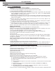
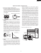
CONNECTOR (NO-CASE TYPE) REMOVAL
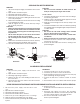
Figure C-2. Positive lock
®
connector
1. Disconnect the power supply cord, and then remove
outer case.
2. Open the door and block it open.
3. Discharge high voltage capacitor.
4. Push the lever of positive lock
®
connector.
5. Pull down on the positive lock
®
connector.
CAUTION: WHEN CONNECTING THE POSITIVE LOCK
®
CONNECTORS TO THE TERMINALS, CON-
NECT THE POSITIVE LOCK
®
SO THAT THE
LEVER FACES YOU.
1. Disconnect the power supply cord and then remove outer
case.
2. Open the door and block it open.
3. Discharge high voltage capacitor.
4. Disconnect the wire leads from panel components.
5. Remove the one (1) screw holding the control panel
assembly to the oven cavity front plate.
6. Slide the control panel assembly upward and remove
it.
7. Now, individual components can be removed.
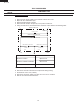
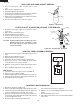
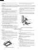
PWB Removal:
1. Lay Control Panel on pretect surface with PWB up.
2. Remove 4 scews shown in Fig 3.
3. Lift plastic ribbon holder to release ribbon out of connector.
4. Release tabs from PSU (4) and LSI (2) and lift each off.
5. The PWB is now free to replace.
2. Remove turntable and turntable support from oven cavity.
3. Lay the oven on it's backside. Remove the turntable motor
cover by snipping off the material in four corners.
4. Where the corners have been snipped off bend corner
areas flat. No sharp edges must be evident after removal
of the turntable motor cover.
5. Disconnect wire leads from turntable motor.
TURNTABLE MOTOR REMOVAL
1. Disconnect the power supply cord.
(See "Positive lock connector removal")
6. Remove one (1) screw holding turntable motor to oven
cavity.
7. Now the turntable motor is free.
8. After replacement use the one (1) screw to fit the turntable
motor cover.
1.
Disconnect the power supply cord and remove outer
case.
2. Open the door and block it open.
3. Discharge high voltage capacitor.
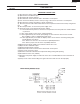
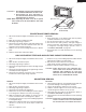
4. Remove the wire leads from the oven lamp the terminal
by pushing on the positive lock lever (Fig C-1).
5. Remove the screw holding the oven lamp, then remove
lamp from the magnetron duct.
6. Now, the oven lamp is free to check or replace.
OVEN LAMP AND LAMP SOCKET REMOVAL
Figure C-1. Oven lamp
Terminal
Push
Pull down
1
2
Lever
Positive lock¨
connector
Terminals
Oven lamp
Screw
Screw
Screw
Screw
Screw
Tab
Tab
Tab
Tab
Tab
Tab
Ribbon connector
LSI
PSU
Figure 3. PWB Removal