
Operation Manual


letter N (neutral) = blue coloured wire;
symbol” ” earth = green-yellow coloured wire;
- The electric cable must be positioned so that it cannot reach a temperature of over 75 K at any point.
- Do not use reducers, adapters or shunts for the connection as they could cause false contacts and
subsequent dangerous overheating.
When the connection is made directly with the electricity supply:
-To connect the appliance directly to the supply mains, a means for disconnection having a contact
separation in all poles that provide full disconnection under overvoltage category III conditions, must be
incorporated in the fixing wiring, according with the wiring rules.
- Remember that the earth wire must not be interrupted by the switch.
- Alternatively the electrical connection can also be protected by a differential switch of high sensitivity.
- You are strongly advised to fix the special yellow-green earth wire to an efficient earthing system
ATTENTION: The appliance conforms with the regulations of directives 90/396EEC (Gas Directive)
regarding gas appliances for domestic use and the like, 93/68 and 73/23 (Low Voltage Directive) regarding
electrical safety and 2004/108/CE, 93/68 and 89/336 (EMC Directive) regarding electromagnetic
compatibility.
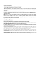
Wiring diagrams Wiring diagram description
For hotplate see Fig. 13. 1. Cable terminal L. Black
2. Ignition switch N. White
3. Spark generator T. Green (earth)
4. Ignition spark
MAINTENANCE OF THE MACHINE
CHANGING THE PARTS
Before carrying out any maintenance work, disconnect the appliance from the gas and electric
supply.
To replace different components such as burners, taps and electrical parts you must take out the hob from
the kitchen unit by releasing the fixing hooks, unscrew the fixing screws of the burners on the work top,
unscrew the fixing nuts of the electric plates which are visible on the lower part of the hob and remove the
worktop in order to carry out the replacement of the defective parts.
NOTE: If the taps need replacing you also need to unscrew the two fixing screws of the gas ramp at the
bottom of the hob which are found on the upper part of the latter.
For appliances equipped with automatic “ON” switches you must dismantle the “ON” switch chain before
replacing the taps.
You are advised to change the seal on the tap every time you replace a tap in order to ensure a perfect hold
between the body and ramp.
WARNING: The electric cable which is provided with the appliance is connected to the appliance with a type
X connection and thus can be replaced with the same type of cable as that installed without using special
tools.
In the event of wear or damage to the mains cable, replace it with :
Type/ section of mains cable H05VV-F 3x0,75 mm2 or H05RR-F 3x0,75mm2
WARNING: If you replace the electric mains cable the installer must have the earth conductor about 2
cm longer than the phase conductors and must also take heed of the warnings regarding electric
connection.
Room ventilation – Location and venting.
ATTENTION: An exhaust fan may be used with the appliance; in each case it shall be installed in
conformity with the national standards in force.
ATTENTION: Exhaust hood operation may affect other vented appliances; in each case it shall be
installed in conformity with the national standards in force.
- CHANGING THE NOZZLES FOR USE WITH OTHER TYPES OF GAS:
To change the nozzles of the burners use the following procedure: