
Installation Manual

14
/ Gas connection
Warning!
DO NOT USE AN OPEN FLAME WHEN
CHECKING FOR LEAKS!
Leak testing of the appliance shall be conducted
according to the manufacturer’s instructions. Be-
fore placing the oven into operation, always check
for leaks with soapy water solution or other accep-
table method.
Check for gas leakage with soapy water solution or
other acceptable methods in all gas connections
installed between inlet gas pipe of the appliance,
gas regulator, till to the manual shut-off valve.
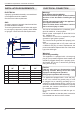
All gas connections must comply with national and
local codes. The gas supply line (service) must
be the same size or greater than the inlet line of
the appliance. This cooktop uses a 1/2” NPT inlet
(see drawing below for details of gas connection).
On all pipe joints use appropriate sealant resistant
to gas to joint the adapter to rangetop manifold
use only the blue gasket supplied.
If necessary, the appliance must be converted by
the dealer, by a factory-trained professional or by
a qualifi ed licensed plumber or gas service com-
pany.
Gas conversion is important for safe and eff ective
use of the appliance. It is the responsibility of the
dealer and the owner of the cooktop to perform
the appropriate gas conversion following the di-
rections of the manufacturer.
THE GAS CONVERSION PROCEDURE IS
DESCRIBED IN THIS MANUAL AND IN THE
PACKAGE CONTAINING THE CONVERSION
NOZZLES SHIPPED WITH EVERY RANGE.
Please provide the service person with this ma-
nual before work is started on the range.
MANUAL SHUT-OFF VALVE
THIS VALVE IS NOT SHIPPED WITH THE AP-
PLIANC AND MUST BE SUPPLIED BY THE IN-
STALLER.
The manual shut-off valve must be installed in the
gas service line between the gas hook-up on the
wall and the appliance inlet, in a position where it
can be reached quickly in the event of an emer-
gency.
In Massachusetts: A ‘T’ handle type manual
gas valve must be installed in the gas supply line
to this appliance.
FLEXIBLE CONNECTIONS
In case of installation with fl exible couplings and/
or quick-disconnect fi ttings, the installer must use
a heavy-duty, AGA design-certifi ed commercial
fl exible connector of at least 1/2” (1.3 cm) ID NPT
(with suitable strain reliefs) in compliance with
ANSI Z21.41 and Z21.69 standards.
In Massachusetts: The unit must be installed
with a 36” (3-foot) long fl exible gas connector.
In Canada: use CAN 1-6.10-88 metal connec-
tors for gas appliances and CAN 1-6.9 M79 quick
disconnect device for use with gas fuel.
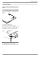
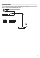
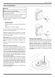
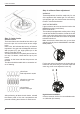
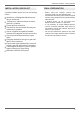
PRESSURE TEST-POINT STOPPER
VALVE
To avoid gas leaks, the pressure test-point stop-
per valve and gasket supplied with the range must
be installed on the gas fi tting at the back of the
range according to the diagram below.
GAS CONNECTION
GAS PIPE
GASKET
PRESSURE TEST-POINT
STOPPER
GAS CONNECTION ADAPTOR
1/2’’NPT WITH PRESSURE TEST
POINT 1/8’’ NPT (TO BE FIXED
TOWARD EXTERNAL SIDE OF
THE APPLIANCE)
ELBOW