BERTAZZONI INSTALLATION MANUAL FREESTANDING DUAL FUEL RANGES 3100293 WWW.BERTAZZONI.
/ Table of contents TABLE OF CONTENTS WARNINGS ___________________________________________________________________ DATA RATING LABEL ___________________________________________________________ BEFORE INSTALLATION ________________________________________________________ VENTILATION PREPARATION ____________________________________________________ SPECIFICATIONS ______________________________________________________________ CLEARENCE DIMENSIONS ______________________________________________________ INSTALLATI
/ Models Models Models MAST305DFMBIE PROF304DFSART MAST305DFMNEE PROF304DFSBIT MAST305DFMXE PROF304DFSGIT MAST365DFMBIE PROF304DFSNET MAST365DFMNEE PROF304DFSROT MAST365DFMXE PROF304DFSXT MAST366DFSXT PROF366DFSART MAST486GDFSXT PROF366DFSBIT PROF366DFSGIT PROF366DFSNET PROF366DFSROT PROF366DFSXT PROF486GDFSART PROF486GDFSBIT PROF486GDFSGIT PROF486GDFSNET PROF486GDFSROT PROF486GDFSXT 3
/ Warnings WARNINGS To ensure proper and safe operation, the appliance must be properly installed and grounded by a qualified technician. DO NOT attempt to adjust, repair, service, or replace any part of your appliance unless it is specifically recommended in this manual. All other servicing should be referred to a qualified servicer. Have the installer show you the location of the gas shutoff valve and how to shut it off in an emergency.
/ Warnings/ Data rating label Engage the range to the anti-tip device by anti-tip brackets or anti-tip chain (see installing the anti-tip device chapter). Ensure the anti-tip device is re-engaged when the range is moved. Re-engage the anti-tip device if the range is moved. Do not operate the range without te anti-tipdevice in place and engaged. See anti-tip device installation instructions for details. DATA RATING LABEL The data rating label shows the model and serial number of the range.
/ Before installation BEFORE INSTALLATION • This appliance shall only be installed by an authorized professional. • This appliance shall be installed in accordance with the manufacturer’s installation instructions. • This appliance must be installed in accordance • • with the norms & standards of the country where it will be installed. The installation of this appliance must conform to local codes and ordinances.
/ Ventilation preparation / Specifications VENTILATION PREPARATION Hood Placement: This range will best perform when installed with Bertazzoni exhaust hoods. These hoods have been designed to work in conjunction with the Bertazzoni range and have the same finish for a perfect look. Before installation of the exhaust hood, consult local or regional building and installation codes for additional specific clearance requirements.
/ Specifications Burner Auxiliary Semi-rapid Rapid Dual burner Injector Gas Pressure Max Rate diam.[mm] Type [iwc] [Btu/hr] [W] 0.90 0.54 1.18 0.70 1.55 0.92 0.80+2.10 0.50+1.20 NG LP (Propane) NG LP (Propane) NG LP (Propane) NG LP (Propane) 4’’ 10’’ 4’’ 10’’ 4’’ 10’’ 4’’ 10’’ 3,500 3,300 5,900 5,500 10,400 9,500 19000 19000 1,025 967 1,728 1,611 3,046 2,783 5,567 5,567 By-pass Min Rate [Btu/hr] [W] diam.
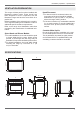
/ Clearence dimensions CLEARENCES DIMENSIONS Installation adjacent to kitchen cabinets This range may be installed directly adjacent to existing countertop high cabinets (36” or 91.5 cm from the floor). For the best look, the worktop should be level with the cabinet countertop. This can be accomplished by raising the unit using the adjustment spindles on the legs.
/ Installation requirements / Electrical connection INSTALLATION REQUIREMENTS ELECTRICAL A properly-grounded horizontally- mounted electrical receptacle should be installed no higher than 3” (7.6 cm) above the floor, no less than 2” (5 cm) and no more than 8” (20,3 cm) from the left side (facing product). Check all local code requirements. GAS An agency-approved, properly-sized manual shut-off valve should be installed no higher than 3” (7.
/ Installation requirements / Electrical connection FOUR-WIRE CONN.RECEPTACLE NEMA 14-50R The appliance is equipped at the factory with an electric supply cord set 4 wires type with ring terminals (L1, L2, N, Ground) suitable for range use UL/CSA listed type SRDT/DRT 2x6AWG (L1, L2)+2x8AWG (N, G) rated 300V, 40 or 50A with fused plug type NEMA 14-50P; cable length 1,5 m.
/ Wiring diagram WIRING DIAGRAM The electric wiring diagrams and schematics are attached behind the range, and should not be removed except by a service technician, then replaced after service. P1 P2 P3 P4 P5 P6 P7 P8 P1 P2 DFM Simb. IGN COLOURS Simb.
/ Wiring diagram 30 /36 /48 DFS RC FS n bi A B MT a CN30 b to MV RC a CN21 MVT up v r b v MV RP b gr to MV to M-GROUND gr MV RG+RC a bi DL MVT down n n to M-L1 n to M-L1 n to M-L1 K n LF to M-L1 to M-N to GROUND to DL to DL to M-L1 to DL to DL to M-N to M-L1 bi LF r 1 r bi n 2 to M-L1 to CN27 - 6 to CN27 - 5 to CN26 - 2 to CN26 - 3 IGN G bi TSS Simb.
/ Gas connection GAS CONNECTION Warning! FLEXIBLE CONNECTIONS DO NOT USE AN OPEN FLAME WHEN CHECKING FOR LEAKS! In case of installation with flexible couplings and/ or quick-disconnect fittings, the installer must use a heavy-duty, AGA design-certified commercial flexible connector of at least 1/2” (1.3 cm) ID NPT (with suitable strain reliefs) in compliance with ANSI Z21.41 and Z21.69 standards. Leak testing of the appliance shall be conducted according to the manufacturer’s instructions.
/ Gas connection PRESSURE REGULATOR Since service pressure may fluctuate with local demand, every gas cooking appliance must be equipped with a pressure regulator on the incoming service line for safe and efficient operation. The pressure regulator shipped with the appliance has two female threads ½” NPT. The regulator shall be installed properly in order to be accessible when the appliance is installed in its final position.
/ Installation INSTALLATION APPLIANCE INSTALLATION Unpacking the range • Remove all packing materials from the ship- • • • • ping pallet but leave the adhesive-backed foam layer over brushed-metal surfaces to protect it from scratches until the range is installed in its finalposition. Only the film on the side panels should be removed before inserting the range between the cabinets. Examine the appliance after unpacking it. In the event of transport damage, do not plug it.
/ Installation INSTALLING THE LEGS Bertazzoni ranges must be used only with the legs properly installed. Four height-adjustable legs are supplied with the range in the polysterene container situated over the appliance. Before installing the legs, position the appliance near its final location as the legs are not suitable for moving the appliance over long distances. After unpacking the range, raise it enough to insert the legs in the appropriate receptacles situated on the lower part of the appliance.
/ Installation INSTALLING THE ISLAND TRIM INSTALLING BACKGUARD (OPTIONAL) The island trim must be installed prior to operation of the appliance for appropriate ventilation of the oven compartment. The island trim is only placed on the cooktop, remove all tape and packaging before installing it. The backguard must be installed prior to operation of the appliance for appropriate ventilation of the oven compartment. The backguard is an optional contact you dealer for buying it.
/ Installing the anti/tip devices INSTALLING THE ANTI/TIP DEVICES ANTI-TIP BRACKETS ANTI/TILT CHAIN The anti-tip bracket shipped with the range must be properly secured to the rear wall as shown in the picture below. The height of the bracket from the floor must be determined after the range legs have been adjusted to the desired height and after the range has been levelled. Measure the distance from the floor to the bottom of the anti-tip bracket receptacle on the back of the appliance.
/ Gas conversion GAS CONVERSION Warning! Before carrying out this operation, disconnect the appliance from gas and electricity. Gas conversion shall be conducted by a factory-trained professional. Call the customer service hotline to identify a factory-trained professional near your home.
/ Gas conversion Step 4: minimum flame adjustment WARNING! These adjustments should be made only for use of the appliance with natural gas. For use with liquid propane gas, the choke screw must be fully turned in a clockwise direction. Step 3: visual checks Surface burners The burner flame color should be blue with no yellow on the tips. It is not uncommon to see orange in the flame color; this indicates the burning of airborne impurities in the gas and will disappear with use.
/ Installation checklist / final preparation INSTALLATION CHECKLIST A qualified installer should carry out the following checks: Range mounted on its legs Island trim or Backguard attached according to instruction Anti-tip device properly installed Clearance to cabinet surfaces as manufacturer’s guideline Proper ground connection Gas service line connected following manufacturer’s guideline Valves, stoppers and gasket installed between the range and the service line Gas connection tested and free of gas lea
/ Bertazzoni service BERTAZZONI SERVICE Bertazzoni is committed to providing the best customer and product service. We have a dedicated team of trained professionals to answer your needs. If you own a Bertazzoni appliance and need service in the US or Canada please use the following contact information: e-mail: aftersaleservice@bertazzoni.com Telephone - Monday through Friday, 7.30am to 7.30pm EST (except US public holidays).