BERTAZZONI INSTALLATION MANUAL FREESTANDING GAS/ELECTRIC RANGES 3100293 WWW.BERTAZZONI.
/ Table of contents TABLE OF CONTENTS WARNINGS ___________________________________________________________________ DATA RATING LABEL ___________________________________________________________ BEFORE INSTALLATION ________________________________________________________ VENTILATION PREPARATION ____________________________________________________ SPECIFICATIONS ______________________________________________________________ CLEARENCE DIMENSIONS ______________________________________________________ INSTALLATI
/ Models Models Models MAST305DFMBIE PROF304DFSART MAST305DFMNEE PROF304DFSBIT MAST305DFMXE PROF304DFSGIT MAST365DFMBIE PROF304DFSNET MAST365DFMNEE PROF304DFSROT MAST365DFMXE PROF304DFSXT MAST366DFSXT PROF366DFSART MAST486GDFSXT PROF366DFSBIT PROF366DFSGIT PROF366DFSNET PROF366DFSROT PROF366DFSXT PROF486GDFSART PROF486GDFSBIT PROF486GDFSGIT PROF486GDFSNET PROF486GDFSROT PROF486GDFSXT 3
/ Warnings WARNINGS To ensure proper and safe operation, the appliance must be properly installed and grounded by a qualified technician. DO NOT attempt to adjust, repair, service, or replace any part of your appliance unless it is specifically recommended in this manual. All other servicing should be referred to a qualified servicer. Have the installer show you the location of the gas shutoff valve and how to shut it off in an emergency.
/ Warnings/ Data rating label Re-engage the anti-tip device if the range is moved. Do not operate the range without te anti-tipdevice in place and engaged. Do not use the range if the anti-tip device has not been properly installed and engaged. See installation instructions for details. DATA RATING LABEL The data rating label shows the model and serial number of the range.
/ Before installation BEFORE INSTALLATION • This appliance shall only be installed by an authorized professional. • This appliance shall be installed in accordance with the manufacturer’s installation instructions. • This appliance must be installed in accordance • • with the norms & standards of the country where it will be installed. The installation of this appliance must conform to local codes and ordinances.
/ Ventilation preparation / Specifications VENTILATION PREPARATION Hood Placement: This range will best perform when installed with Bertazzoni exhaust hoods. These hoods have been designed to work in conjunction with the Bertazzoni range and have the same finish for a perfect look. Before installation of the exhaust hood, consult local or regional building and installation codes for additional specific clearance requirements.
/ Specifications Burner Auxiliary Semi-rapid Rapid Dual burner Injector Gas Pressure Max Rate diam.[mm] Type [iwc] [Btu/hr] [W] 0.90 0.54 1.18 0.70 1.55 0.92 0.80+2.10 0.50+1.20 NG LP (Propane) NG LP (Propane) NG LP (Propane) NG LP (Propane) 4’’ 10’’ 4’’ 10’’ 4’’ 10’’ 4’’ 10’’ 3,500 3,300 5,900 5,500 10,400 9,500 19000 19000 1,025 967 1,728 1,611 3,046 2,783 5,567 5,567 By-pass Min Rate [Btu/hr] [W] diam.
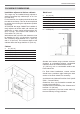
/ Clearence dimensions CLEARENCE DIMENSIONS Installation adjacent to kitchen cabinets This range may be installed directly adjacent to existing countertop high cabinets (36” or 91.5 cm from the floor). For the best look, the worktop should be level with the cabinet countertop. This can be accomplished by raising the unit using the adjustment spindles on the legs.
/ Installation requirements / Electrical connection INSTALLATION REQUIREMENTS ELECTRICAL A properly-grounded horizontally- mounted electrical receptacle should be installed no higher than 3” (7.6 cm) above the floor, no less than 2” (5 cm) and no more than 8” (20,3 cm) from the left side (facing product). Check all local code requirements. GAS An agency-approved, properly-sized manual shut-off valve should be installed no higher than 3” (7.
/ Installation requirements / Electrical connection FOUR-WIRE CONN.RECEPTACLE NEMA 14-50R The appliance is equipped at the factory with an electric supply cord set 4 wires type with ring terminals (L1, L2, N, Ground) suitable for range use UL/CSA listed type SRDT/DRT 2x6AWG (L1, L2)+2x8AWG (N, G) rated 300V, 40 or 50A with fused plug type NEMA 14-50P; cable length 1,5 m.
/ Wiring diagram WIRING DIAGRAM The electric wiring diagrams and schematics are attached behind the range, and should not be removed except by a service technician, then replaced after service. P1 P2 P3 P4 P5 P6 P7 P8 P1 P2 DFM Simb. IGN COLOURS Simb.
/ Wiring diagram 30 /36 /48 DFS RC FS n bi A B MT a CN30 b to MV RC a CN21 MVT up v r b v MV RP b gr to MV to M-GROUND gr MV RG+RC a bi DL MVT down n n to M-L1 n to M-L1 n to M-L1 K n LF to M-L1 to M-N to GROUND to DL to DL to M-L1 to DL to DL to M-N to M-L1 bi LF r 1 r bi n 2 to M-L1 to CN27 - 6 to CN27 - 5 to CN26 - 2 to CN26 - 3 IGN G bi TSS Simb.
/ Gas connection GAS CONNECTION Warning! FLEXIBLE CONNECTIONS DO NOT USE AN OPEN FLAME WHEN CHECKING FOR LEAKS! In case of installation with flexible couplings and/ or quick-disconnect fittings, the installer must use a heavy-duty, AGA design-certified commercial flexible connector of at least 1/2” (1.3 cm) ID NPT (with suitable strain reliefs) in compliance with ANSI Z21.41 and Z21.69 standards. Leak testing of the appliance shall be conducted according to the manufacturer’s instructions.
/ Gas connection PRESSURE REGULATOR Since service pressure may fluctuate with local demand, every gas cooking appliance must be equipped with a pressure regulator on the incoming service line for safe and efficient operation. The pressure regulator shipped with the appliance has two female threads ½” NPT. The regulator shall be installed properly in order to be accessible when the appliance is installed in its final position.
/ Installation INSTALLATION APPLIANCE INSTALLATION Unpacking the range • Remove all packing materials from the ship- • • • • ping pallet but leave the adhesive-backed foam layer over brushed-metal surfaces to protect it from scratches until the range is installed in its finalposition. Only the film on the side panels should be removed before inserting the range between the cabinets. Examine the appliance after unpacking it. In the event of transport damage, do not plug it.
/ Installation INSTALLING THE LEGS Bertazzoni ranges must be used only with the legs properly installed. Four height-adjustable legs are supplied with the range in the polysterene container situated over the appliance. Before installing the legs, position the appliance near its final location as the legs are not suitable for moving the appliance over long distances. After unpacking the range, raise it enough to insert the legs in the appropriate receptacles situated on the lower part of the appliance.
/ Installation INSTALLING THE ISLAND TRIM INSTALLING BACKGUARD (OPTIONAL) The island trim must be installed prior to operation of the appliance for appropriate ventilation of the oven compartment. The island trim is only placed on the cooktop, remove all tape and packaging before installing it. The backguard must be installed prior to operation of the appliance for appropriate ventilation of the oven compartment. The backguard is an optional contact you dealer for buying it.
/ Installing the anti/tip devices INSTALLING THE ANTI/TIP DEVICES ANTI-TIP BRACKETS ANTI/TILT CHAIN The anti-tip bracket shipped with the range must be properly secured to the rear wall as shown in the picture below. The height of the bracket from the floor must be determined after the range legs have been adjusted to the desired height and after the range has been levelled. Measure the distance from the floor to the bottom of the anti-tip bracket receptacle on the back of the appliance.
/ Gas conversion GAS CONVERSION Warning! Before carrying out this operation, disconnect the appliance from gas and electricity. Gas conversion shall be conducted by a factory-trained professional. Call the customer service hotline to identify a factory-trained professional near your home.
/ Gas conversion Step 4: minimum flame adjustment WARNING! These adjustments should be made only for use of the appliance with natural gas. For use with liquid propane gas, the choke screw must be fully turned in a clockwise direction. Step 3: visual checks Surface burners The burner flame color should be blue with no yellow on the tips. It is not uncommon to see orange in the flame color; this indicates the burning of airborne impurities in the gas and will disappear with use.
/ Installation checklist / final preparation INSTALLATION CHECKLIST A qualified installer should carry out the following checks: Range mounted on its legs Island trim or Backguard attached according to instruction Anti-tip device properly installed Clearance to cabinet surfaces as manufacturer’s guideline Proper ground connection Gas service line connected following manufacturer’s guideline Valves, stoppers and gasket installed between the range and the service line Gas connection tested and free of gas lea
/ Bertazzoni service BERTAZZONI SERVICE Bertazzoni is committed to providing the best customer and product service. We have a dedicated team of trained professionals to answer your needs. If you own a Bertazzoni appliance and need service in the US or Canada please use the following contact information: e-mail: aftersaleservice@bertazzoni.com Telephone - Monday through Friday, 7.30am to 7.30pm EST (except US public holidays).
/ Assistance Bertazzoni ASSISTANCE BERTAZZONI Bertazzoni s'engage à fournir le meilleur service clients et la meilleure assistance produits possibles. Notre équipe de professionnels dévoués et formés répondra à vos besoins. Si vous disposez d'un appareil Bertazzoni et souhaitez bénéficier d'une assistance aux États-Unis ou au Canada, utilisez les coordonnées suivantes : e-mail : aftersaleservice@bertazzoni.com Tél. - Lundi au vendredi, 7h30 à 19h30 EST (sauf jours fériés aux États-Unis).
/ Liste de contrôle pour l'installation / Préparation finale LISTE DE CONTRÔLE POUR L'INSTALLATION Un installateur qualifié devra réaliser les contrôles suivants : La cuisinière est-elle installée sur ses pieds ? La garniture ou la protection arrière est-elle fixée conformément aux instructions fournies ? Les dispositifs anti-basculement sont-ils correctement installés ? Le dégagement par rapport aux surfaces des meubles est-il conforme aux consignes du fabricant ? Le raccordement à la terre a-t-il été corre
Étape 3 : contrôles visuels Brûleurs de la surface de cuisson La flamme du brûleur doit être bleue, sans coloration jaune aux extrémités. Il n'est pas rare de voir de l'orange sur la flamme. Cela indique la combustion d'impuretés en suspension dans le gaz et disparaîtra pendant l'utilisation. Avec du gaz propane (LPG), il est normal de voir de petites pointes jaunes sur les premières flammes. La combustion de la flamme doit être complète autour du chapeau du brûleur.
/ Conversion à un autre type de gaz CONVERSION À UN AUTRE TYPE DE GAZ Avertissement ! Avant de réaliser cette opération, débrancher l'appareil de l'alimentation en gaz et en électricité. La conversion doit être effectuée par un professionnel formé à cet effet par le fabricant. Appeler le service clients pour trouver le professionnel formé par le fabricant le plus proche.
/ Installation des dispositifs anti-basculement INSTALLATION DES DISPOSITIFS ANTI-BASCULEMENT La chaîne anti-basculement doit être fixée au côté gauche ou droit, selon les instructions ci-après. Tirer la chaîne manuellement à travers l'anneau et l'insérer dans le crochet. Défaire la chaîne avant tout déplacement de la cuisinière en vue d'une opération d'entretien. Les supports anti-basculement fournis avec la cuisinière doivent être correctement fixés au mur postérieur, comme indiqué sur la figure cidessous.
/ Installation INSTALLATION DE LA GARNITURE La garniture doit être installée avant toute utilisation de la cuisinière afin de garantir la ventilation appropriée du compartiment du four. La garniture est uniquement positionnée sur la surface de cuisson. Retirer tous les rubans et matériaux d'emballage avant son installation. Avant l’installation, portez des gants de sécurité.
INSTALLATION DES PIEDS Les cuisinièresBertazzoni ne doivent être utilisées qu'une fois leurs pieds correctement installés. Quatre pieds réglables en hauteur sont fournis avec la cuisinière dans le conteneur en polystyrène placé sur le dessus de l'appareil. Avant d'installer les pieds, positionner la cuisinière à proximité de son emplacement final ; les pieds ne doivent pas être utilisés pour la déplacer sur de longues distances.
/ Installation INSTALLATION INSTALLATION DE L'APPAREIL Déballage de la cuisinière • • • • Retirer tous les matériaux d'emballage de la paletted'expédition sans toucher à la mousse postérieure adhésive sur les surfaces en métal brossé, afin de protéger la cuisinière des rayures jusqu'à son installation à son emplacement final. Ne retirer que le film protégeant les panneaux latéraux avant de positionner la cuisinière entre les meubles de cuisine. Examiner la cuisinière après l'avoir déballée.
/ Raccordement au gaz RÉGULATEUR DE PRESSION Dans la mesure où la pression de service peut fluctuer en fonction de la demande locale, chaque appareil de cuisson au gaz doit être équipé d'un régulateur de pression sur la conduite d'alimentation, pour garantir un fonctionnement sûr et efficace. Le régulateur de pression fourni avec l'appareil dispose de deux filetages femelles ½” NPT. Le régulateur doit être correctement installé afin d'être accessible une fois l'appareil installé dans son emplacement final.
/ Raccordement au gaz RACCORDEMENT AU GAZ Avertissement ! NE PAS UTILISER DE FLAMME LIBRE POUR RECHERCHER LES FUITES DE GAZ ! La recherche de fuites sur la cuisinière doit être réalisée conformément aux instructions du fabricant. Avant d'utiliser le four, toujours réaliser une recherche de fuites avec une solution d'eau savonneuse ou toute autre méthode valide.
CMV up Description Black n Blue Orange a White Grey gr b Violet v bi Red Green r Brown gv m Simb.
/ Schéma de câblage SCHÉMA DE CÂBLAGE Les schémas de câblage électrique figurent à l'arrière de la cuisinière et ne peuvent être retirés que par un technicien de maintenance, qui doit les remettre en place une fois l'entretien réalisé. 30 /36 DFM P1 P2 P3 P4 P5 P6 P7 P8 P1 P2 LEGENDA Simb. IGN COLOURS Simb.
RECEPTACLE DE CONNEXION A QUATRE FILS (NEMA 14-50R) RECEPTABLE DE CONNEXION A TROIS FILS (NEMA 14-50R) / Conditions d'installation / Raccordement électrique NE PAS UTILISER DE RALLONGE AVEC CET APPAREIL. LE FAIRE PEUT ENTRAINER UN INCENDIE, UN CHOC ELECTRIQUE OU AUTRE DOMMAGE CORPOREL.
/ Conditions d'installation / Raccordement électrique CONDITIONS D'INSTALLATION ÉLECTRICITÉ Une prise électrique montée horizontalement et correctement mise à la terre doit être installée à une hauteur maximale de 3” (7,6 cm) et minimale de 2” (5 cm) par rapport au sol, et à une distance maximale de 8” (20,3 cm) par rapport au côté gauche du produit (en lui faisant face). Vérifier les dispositions des règlementations locales.
/ Espace de dégagement ESPACE DE DÉGAGEMENT Installation adjacente à des meubles de cuisine Cette cuisinière peut être installée à proximité directe de plans de travail avec meubles intégrés (36” ou 91,5 cm par rapport au sol). Pour un aspect optimal, la surface de la cuisinière doit être au même niveau que celle du plan de travail avec meuble intégré. Pour ce faire, régler la hauteur de l'appareil en agissant sur les dispositifs de réglage des pieds.
/ Spécifications Brûleur Injecteur Gaz diam. [mm] Type Auxiliaire Semi-rapide Rapide Double brûleur 0.90 0.54 1.18 0.70 1.55 0.92 0.80+2.10 0.50+1.
/ Préparation de la ventilation / Spécifications PRÉPARATION DE LA VENTILATION Cette cuisinière a un fonctionnement optimal en cas d'installation avec une hotte d'extraction Bertazzoni. Ces hottes, conçues pour être associées à la gamme Bertazzoni, offrent un aspect impeccable grâce à leur finition identique. Avant d'installer la hotte d'extraction, consulter les règlementations locales ou régionales en matière de construction et d'installation pour connaître les critères spécifiques aux espaces de dégagement.
/ Avant l'installation AVANT L'INSTALLATION • • • • • L'appareil doit être installé uniquement par un professionnel autorisé. Cet appareil doit être installé conformément aux instructions d'installation du fabricant. L'appareil doit être installé conformément aux normes et aux règlementations du pays d'installation. L'installation de cet appareil doit être conforme aux règlementations locales.
Remettre en place les dispositifs anti-basculement après tout déplacement de la cuisinière. Ne pas utiliser la cuisinière si les dispositifs anti-basculement ne sont pas en place et enclenchés. Ne pas utiliser la cuisinière si les dispositifs anti-basculement n'ont pas été correctement installés et enclenchés. Pour plus d'informations, consulter les instructions d'installation.
/ Avertissements AVERTISSEMENTS Pour un fonctionnement correct et en toute sécurité, l'appareil doit être correctement installé et mis à la terre par un technicien qualifié. NE PAS tenter de régler, réparer, réviser ou remplacer un composant de l'appareil à moins que le présent manuel ne le recommande spécifiquement. Toute autre intervention doit être réalisée par un opérateur qualifié. L'installateur montrera l'emplacement de la vanne de fermeture du gaz et les modalités d'arrêt en cas d'urgence.
PROF366DFSBIT MAST486GDFSXT PROF366DFSART MAST366DFSXT PROF304DFSXT MAST365DFMXE PROF304DFSROT MAST365DFMNEE PROF304DFSNET MAST365DFMBIE PROF304DFSGIT MAST305DFMXE PROF304DFSBIT MAST305DFMNEE PROF304DFSART MAST305DFMBIE Modèles Modèles / Modèles PROF366DFSGIT PROF366DFSNET PROF366DFSROT PROF366DFSXT PROF486GDFSART PROF486GDFSBIT PROF486GDFSGIT PROF486GDFSNET PROF486GDFSROT PROF486GDFSXT 3
/ Table des matières TABLE DES MATIÈRES AVERTISSEMENTS ____________________________________________________________ ÉTIQUETTE SIGNALÉTIQUE _____________________________________________________ AVANT L'INSTALLATION ________________________________________________________ PRÉPARATION DE LA VENTILATION ______________________________________________ SPÉCIFICATIONS ______________________________________________________________ ESPACE DE DÉGAGEMENT ______________________________________________________ CONDITION
BERTAZZONI MANUEL D'INSTALLATION CUISINIÈRES À GAZ/ELECTRIQUE AUTONOMES 3100293 WWW.BERTAZZONI.