REF30PIXL REF30PIXR REF30PRL REF30PRR REF36PIXL REF36PIXR REF36PRL REF36PRR INSTALLATION GUIDE EN NOTICE D’INSTALLATION FR
IMPORTANT Dimensions in parentheses are in inches: mm(in). Weights in parentheses are in pounds: kg (lb).
Installation Guide Index Important Instructions Page 3 Important safety instructions Children safety Technical Requirements 4 Appliance features and installation requirements 5 Installation niche features: Integrated Series (BI) 6 Installation niche requirements: Stainless Integrated Series (BKI) 7 Transport to installation site and unpacking 8 Electrical and Water connection 10 English Preparing To Install Levelling Panels Mounting 11 Door and Bottom-Drawer overlay panels layout 13 Over
2
Installation Guide Series: All Important safely instruction Symbols used in the Guide Note Tips for the correct use of the appliance Important Directions to avoid appliance damage Warning Directions to prevent injury DANGER: Risk of child entrapment. Before you throw away your old refrigerator or freezer: • Take off the doors • Leave the shelves in place so that children may not easily climb inside.
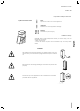
StandPlus/ X-pro Description Integrated Classic Appliance Fasteners, brackets, screws, wrench for mounting outer panels Alluminium trims to fill gap between appliance and cabinets Owner’s Kit (inside the appliance) Maker - Models with Ice Maker Description Maker - Models without Ice Maker Water fill hose (only models with Ice Maker) Water filter (only models with Ice Maker) Leveling feet Anti-tipping brackets, fixing plugs and screws Appliance cleaning kit User Manual, Installation Guide, Guarantee C
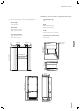
Installation Guide Installation niche features: Integrated Series (BI) A area to be left clear for the anti-tipping brackets Door Opening Angle 105° Niche Height Width 2134 mm (84”) BI36: 899 mm (35 3/8”) BI30: 749 mm (29 1/2”) Niche Width BI36: 900 mm (35 1/2”) BI30: 750 mm (29 5/8”) Height 2120 mm (83 1/2”) + 25 mm (1”) Door Swing Clearance Depth with door (without panel) A English A BI36: 160 (6 3⁄8”) BI30: 125 (5”) BI36: 1470 (57 7⁄8”) BI30: 1320 (52”) 992 (39”) 140 (5 ½”) 100 (4”) 140 (5
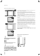
Series: All Installation niche requirements: Stainless Integrated Series (BKI) A area to be left clear for the anti-tipping brackets Door Opening Angle 105° Niche Height Width 2134 mm (84”) BKI36: 899 mm (35 3/8”) BKI30: 749 mm (29 1/2”) Niche Width BKI36: 900 mm (35 1/2”) BKI30: 750 mm (29 5/8”) Height 2120 mm (83 1/2”) + 25 mm (1”) Door Swing Clearance Depth with door (without panel) A A BKI36: 230 (9”) BKI30: 195 (7 ¾”) BKI36: 1470 (57 7⁄8”) BKI30: 1320 (52”) 140 (5 ½”) 100 (4”) 140 (5 ½”)
Installation Guide Series: All Preparing the installation Transport to installation site and unpacking Since this is a large and heavy appliance, before transporting the appliance, check the access to the location where it will be installed (door size, manoeuvring space in stairwells, etc.). The appliance should always be transported in an erect position. If this is not possible, transport the appliance laying on its rear side.
Series: All Electrical and Water connection E W E W E The appliances are delivered from the factory for operation at 110V120V AC - 60Hz (US and Canada). Do not connect the refrigerator to any GFCI receptacle. They are provided with a suitable supply cable and plug to be connected to an appropriate 15A socket (US and Canada) provided with an effective grounding.
Installation Guide Series: All Back of appliance Electrical connection English Water connection Français Operate as follows: Unwind the electric cable and connect it directly to the wall socket. Make sure the appliance is in the Stand-by condition and that all lights are off; should it be not so press the Unit button to switch it off. Push the 1/4” source waterline fully into the elbow connector then thread the elbow adapter to the solenoid at the back of the appliance.
Series: All Levelling Adjust the appliance level by means of the front levelling feet and the rear adjustable wheels. Operate as follows: The grille should ship taped to the back of the appliance. If by chance it is already in place, remove the grille (it is kept in position by magnets), adjust the height of the levelling feet 1 by means of a 17 mm (3/4”) wrench. 2 1 10 Then adjust the height of the rear wheels by turning the front adjusting bolts 2 clockwise or counter-clockwise as it may be required.
Installation Guide Series: Integrated (BI) Door and Bottom-Drawer overlay panels layout The dimensions of the panels are indicated in the table and drawings on pages 13. Nevertheless, according to the requirements for aligning with other kitchen structures, the door panel can be higher than the upper edge of the refrigerator door, and the drawer panel can be lower than the edge of the drawer.
Series: Integrated (BI) 4 Position the brackets on each set of marks to make sure they are aligned 4 , you may wish to drill pilot holes (pay close attention to the panel’s thickness) 5 . Screw the brackets in place 6 . 5 Drawer Panel When preparing the Drawer Panel, follow the same instructions as per the door panel, but make sure measurements are taken starting from the top edge 7 . The support bracket faces the opposite way 8 (note imgs 4 and 8).
Installation Guide Series: Integrated Overlay panels mounting brackets layout Series 30 A 897 (35 ¼”) 747 (29 3⁄8”) B 417 (16 3⁄8”) 342 (13 ½”) C 354.5 (14”) 279.5 (11”) 597 (23 ½”) 203.5(8”) English Series 36 Holes positions Note: All lateral bracket placement measurements go from the center line to the outside bracket hole A B 6,5 (¼”) B 6,5 (¼”) Door panel Français min 1390 (54 ¾”) Back of the panel 157 (6 ¼”) 660 (26”) Vertical adjustment bracket for upper door. Note orientation.
Series: Integrated (BI) Panels Dimensions Panels can have thickness ranging between 18 mm (3/4”) and 28 mm (1-1/8“). Door panels can have a maximum weight 23 kg (51 lbs) and drawer panels may be a maximum weight of 11kg (25 lbs) Exceeding these weights could void your warranty for any service issues which can be attributed to overweight panels. The hinging mechanism on appliances is considered to be `Zero-clearance`.
Installation Guide Series: Integrated (BI) Mounting the handles on Integrated units 1 Handles will have to be mounted on the panels before they are applied to the fridge. For overlay panel mounting, remove the screw connecting the stand-offs to the handle bar. The overlay screw will pass through the overlay panel, the stand-off and into the handle bar.
Series: Integrated (BI) Mounting panels to the door and the drawer of Integrated units Install 1 hanger bolt about 3 threads deep and 1 depth set screw flush to foam gasket in each mounting cavity. Once all brackets and small brackets have been applied to the panels, you can begin installing the bottom drawer. 1 Operate as follows: Partially install the adjustment bolt with washer into the two holes in the bottom of the drawer 1 .
Installation Guide Series: Integrated (BI) Ensure the top adjustment L-brackets are aligned and inserted into the cavities at the top of the door 6 . English 6 Make sure all the hanger brackets begin above the hanger bolts and then lower the panel down checking that each hanger bracket has engaged its corresponding hanger bolt. At this point, alignment between the panel and adjacent cabinets can be adjusted using the alignment brackets and small brackets 7 and 8 .
Series: All Installation in cabinet of this height requires that the back of the cabinet de ventilated through the top. Otherwise, an additional 2 inches of cabinet height is required for adequate ventilation. Height of custom side panel can be higher as necessary.
Installation Guide Series: All Built-in installation of two or more appliances Note: top ventilation caps not shown in illustrations 1 Required accessories to be ordered separately: Central connection Kit (KCCITU) Each appliance comes with its own set of side profile trim covers for where the appliance connects to the niche side walls. In side-by-side configurations only 1 side profile trim cover will be needed from each set.
Series: All 5 Once completed the previous steps, push the units in their final position 5 . If the units are to be installed inside a niche or within an enclosed structure, it is not necessary to have additional ventilation at the back of the niche as North American units come with a factory installed ventilation cap on top to prevent overheating.
Installation Guide Anti tipping kit installation 1 22 xx 2 66 xx 22xx 66xx 4 English 3 2x 1 6x 2x 2 Français 6x 2x 2x 6x 6x 3 4 21
Series: Stainless (BKI) Mounting handles on stainless front 1 To mount the handles onto the door and the drawer operate as follows: Operate as follows: Insert the two handle spacers onto the mounting studs already available on the door and the drawer 1 . Ensure the mounting studs are not loose. Screw in the Allen set-screws pre-installed on the handle 2 . 2 The screws must be tightened in by means of a 2.5 mm (1/8”) hex wrench / Allen key.
Installation Guide Series: All Air circulation 36 Series 30 Series A 860 (33 7⁄8”) 740 (29 1⁄8”) B > 100 (4”) C 10 (3⁄8”) 50% Français English A forced air system assures ventilation through a grille positioned in the lower front part of the unit. If the kitchen design includes a kickplate, the latter has to be punched in order to maintain a satisfactory air flow, as described in the drawing.
Series: All Post installation checklist Check that the front levelling feet have been properly installed. Check that the connection to the water system does not have any leaks and that the closing tap is easily accessible. Check that the electrical connection is correctly installed and that the multipole switch and socket are easily accessible. Check the perfect alignment of the appliance with adjacent structures.
Installation Guide Series: All Start up To start the appliance, connect the plug to the electrical mains: at this point, when opening the door, the control panel will usually visualize the message “Stand by”, and all the panel keys be off UNIT FRIDGE To turn on all the appliance compartments, press the Unit button for three seconds. The display will show the message “Initial test” for approx. 2 minutes.
IMPORTANT Les dimensions entre parentheses sont en pouces: mm(in). Les poids entre parenthèses sont en livres: kg(lb). Les temperatures entre parentheses sont en °F: °C (°F).
Notice d’Installation Sommaire Indications importantes Page 3 Indications importantes concernant la sécurité Pour la sécurité des enfants Caractéristiques techniques 4 Caractéristiques de l’appareil et conditions requises pour l’installation 5 Caractéristiques de la niche d’installation: Série Integrated (BI) 6 Caractéristiques de la niche d’installation: Série Inox Integrated (BKI) 7 Transport sur le lieu d’installation et déballage 8 Raccordements électrique et hydraulique 10 English Prépar
2
Notice d’Installation Indications importantes concernant la sécurité Important Indications afin d’éviter tout endommagement de l’appareil Note conseils pour une correcte utilisation de l’appareil Attention indications afin d’éviter toute lésion aux personnes Pour la sécurité des enfants English DANGER : Risque d’enfermement pour les enfants. Avant de jeter un vieux réfrigérateur ou congélateur : • Retirer les portes • Laisser les étagères en place afin d’empêcher que des enfants grimpent dedans.
Caractéristiques de l’appareil et conditions requises pour l’installation Dimensions de l’appareil Integrated BI30 BI36 l: 749 mm (29 1/2”)/ h: 2120 mm (83 1/2”)/ p: 610 mm (24”) l: 899 mm (35 3/8”)/ h: 2120 mm (83 1/2”)/ p: 610 mm (24”) Dimensions de l’appareil Inox Integrated BKI30 BKI36 l: 749 mm (29 1/2”)/ h: 2120 mm (83 1/2”)/ p: 635 mm (25”) l: 899 mm (35 3/8”)/ h: 2120 mm (83 1/2”)/ p: 635 mm (25”) Dimension de enballé Poids avec emballage Série 30” Série 36” Tension d’alimentation Modèle am
Notice d’Installation Caractéristiques de la niche d’installation: Série Integrated (BI) A espace à réserver aux équerres anti-renversement Angle d’ouverture de la porte 105° Hauteur de l’encastrement Largeur 2134 mm (84”) BI36: 899 mm (35 3/8”) BI30: 749 mm (29 1/2”) Largeur de l’encastrement BI36: 900 mm (35 1/2”) BI30: 750 mm (29 5/8”) Hauteur 2120 mm (83 1/2”) + 25 mm (1”) Encombrement avec porte ouverte Profondeur (sans panneau) A English A BI36: 160 (6 3⁄8”) BI30: 125 (5”) BI36: 1470 (57 7
Caractéristiques de la niche d’installation: Série Inox Integrated (BKI) A espace à réserver aux équerres anti-renversement Angle d’ouverture de la porte 105° Hauteur de l’encastrement Largeur 2134 mm (84”) BKI36: 899 mm (35 3/8”) BKI30: 749 mm (29 1/2”) Largeur de l’encastrement BKI36: 900 mm (35 1/2”) BKI30: 750 mm (29 5/8”) Hauteur 2120 mm (83 1/2”) + 25 mm (1”) Encombrement avec porte ouverte Profondeur (sans panneau) A A BKI36: 230 (9”) BKI30: 195 (7 ¾”) BKI36: 1470 (57 7⁄8”) BKI30: 1320 (52”
Notice d’Installation Série: tous Préparation à l’installation Transport sur le lieu d’installation et déballage S’agissant d’un appareil lourd et de grandes dimensions, avant de transporter l’appareil, s’informer sur les modalités d’accès au lieu où il sera installé (dimensions des portes, espaces de mouvement dans les escaliers, etc.). L’appareil est fixé à la base de l’emballage (palette) moyennant quatre boulons amovibles avec une clé de 17 mm (3/4”).
Série: tous Raccordements électrique et hydraulique E W Les appareils sont livrés de l’usine pour le fonctionnement à 230V AC - 50Hz (Europe, Royaume Uni et autres Pays) ou 115V AC - 60Hz (EtatsUnis et Canada). N’utiliser ni rallonges ni adapteurs multiples pour le branchement. Un câble d’alimentation avec fiche équipé d’un contact de terre sont fournis pour la connexion à une prise de 16A (Europe, Royaume Uni et autres Pays) ou de 15A (Etats-Unis et Canada) .
Notice d’Installation Série: tous Arrière de l’appareil Branchement Électrique English Raccordement Hydraulique Français Intervenir de la manière suivante: Dérouler le câble électrique et le brancher directement à la prise murale. Contrôler que l’appareil soit en stand-by et que les voyants soient pour éteinéteints; dans le cas contraire, appuyer sur la touche Unit dre l’appareil. Raccorder le tuyau de l’eau au réfrigérateur dans la zone arrière 1 .
Série: tous Mise à niveau Mettre à niveau l’appareil en réglant les pieds et les roues arrière à la base de l’appareil. Intervenir de la manière suivante: Après avoir enlevé le socle (ou grille) inférieur (il est fixé par des aimants), régler l’hauteur des pieds de mise à niveau 1 en utilisant une clé ouverte de 17 mm (3/4”). Ensuite régler l’hauteur des roues arrière en tournant les boulons de réglage 2 dans le sens horaire ou anti-horaire comme nécessaire.
Notice d’Installation Série: Integrated (BI) Préparation des panneaux décoratifs pour la porte et Grands bacs Les dimensions des panneaux sont indiquées dans le tableau et sur les dessins reportés ci-dessous. Selon les exigences d’alignement avec d’autres meubles de la cuisine, le panneau de la porte du réfrigérateur peut être plus haut par rapport à la ligne supérieure de la porte et le panneau inférieur peut être plus bas par rapport à la ligne inférieure du grand bac.
Série: Integrated (BI) 4 Vérifier la position des trous en appuyant les équerres sur les marques 4 puis pratiquer les trous en faisant attention à l’épaisseur du panneau 5 . Visser les équerres 6 .
Notice d’Installation Série: Integrated Préparation des panneaux décoratifs pour Réfrigérateur avec un Grand bac Série 30 A 897 (35 ¼”) 747 (29 3⁄8”) B 417 (16 3⁄8”) 342 (13 ½”) C 354.5 (14”) 279.5 (11”) 597 (23 ½”) 203.
Série: Integrated (BI) Dimensions des panneaux Il est possible d’utiliser des panneaux avec des épaisseurs allant entre 18 mm (3/4 in) et 28 mm (1 1/8 in). Les panneaux de porte avec un poids max de 23 kg (51 lb) et panneaux de grand bac avec poids max de 11 kg (25 lb) Excéder ces poids pourrait annuler la garantie de tous les problèmes de services qui peuvent être attribués à des panneaux en surpoids. Le mécanisme de charnière sur les appareils est considéré comme `zéro dégagement`.
Notice d’Installation Série: Integrated (BI) Montage des poignées: Sèrie Integrated (BI) 1 Les poignées doivent être montées sur le panneau décoratif de la porte et du grand bac avant que les panneaux ne soient fixés au réfrigérateur. English Intervenir de la manière suivante: Après avoir pratiqué deux trous de 5 mm (1/4”) sur le côté arrière des panneaux, insérer les vis fournies à la distance indiquée sur le tableau, reportée ci-dessous, l’une de l’autre.
Série: Integrated (BI) Fixation des panneaux à la porte et au Grand bac: Sèrie Integrated Aprés avoir appliqué les pattes de fixation et les équerres aux panneaux, commencer l’installation par le tiroir du bas. 1 Intervenir de la manière suivante: 2 Serrer les vis que partiellement aux fixations inférieures 1 .
Notice d’Installation Série: Integrated (BI) Accrocher le panneau aux dispositifs de fixation en insérant dans les crans d’alignement supérieurs 6 . 6 English Il est possible d’ajuster l’alignement du panneau par rapport aux meubles adjacents à l’aide des pattes et des équerres d’alignement 7 et 8 . 7 Alignement vertical: soulever ou abaisser le panneau 9 en vissant ou en dévissant la vis à l’équerre.
Série: tous Montage dans une armoire de cette hauteur exige que l’arrière de l’armoire de ventilation par le haut. Sinon, un 2” supplémentaires de hauteur de l’armoire est requis pour une ventilation adéquate. Hauteur du panneau latéral personnalisé peut être plus élevé que nécessaire. Installation dans la niche Encastrement appareil unique 1 Des profils en aluminium peuvent être utilisés pour fermer les espaces entre l’appareil et les meubles adjacents ou un autre appareil juxtaposé à celui-ci.
Notice d’Installation Série: tous Encastrement combinaison 1 Accessoires nécessaires à commander séparément: Kit raccordement central (KCCIT/KCCIH) Des profils en aluminium peuvent être utilisés pour fermer les espaces entre l’appareil et les meubles adjacents ou un autre appareil juxtaposé à celui-ci. Intervenir de la manière suivante: English Positionner les appareils devant la niche en laissant un espace suffisant pour intervenir sur l’arrière des appareils 1 .
Série: tous Une fois complétés les passages ci-dessus, poussez les appareils dans leur position définitive 6 . Il sera nécessaire de prévoir une cheminée de ventilation à l’arrière de la niche pour garantir une ventilation adèquate. Un écart de 5 mm est suffisant pour éviter tout surchauffement. Assemblez toujours les panneaux frontaux à la porte et aux tiroirs avant de placer l’appareil dans sa position définitive dans la niche ou la structure.
Notice d’Installation Anti tipping kit installation 1 22 xx 2 66 xx 22xx 66xx 4 English 3 2x 1 6x 2x 2 Français 6x 2x 2x 6x 6x 3 4 21
Série: Inox Integrated (BKI) Montage des poignées sur le devant inoxydable 1 Pour fixer les poignées à la porte et au grand bac, intervenir comme indiqué. Intervenir de la manière suivante: Insérer les écarteurs sur les deux goujons présents sur la porte et sur le grand bac 1 . Visser les vis à six pans présentes dans la poignée 2 . 2 Les vis de fixation seront serrées à fond, en utilisant une clé à six pans de 2,5 mm (1/8”).
Notice d’Installation Série: tous Circulation de l’air A Série 36 Série 30 860 (33 7⁄8”) 740 (29 1⁄8”) B > 100 (4”) C 10 (3⁄8”) 50% Français English Un système à air forcé assure la ventilation à travers la grille positionnée dans la dans la partie inférieure de l’appareil. Si l’aménagement de la cuisine prévoit une plinthe, cette dernière doit être trouée afin de garder un niveau d’aréation satisfaisant, comme expliqué dans le dessin.
Série: tous Contrôle de fin d’installation mise en marche Contrôler que les pieds sont correctement installés. Contrôler que le raccordement à l’installation hydrique ne présente pas de fuites d’eau et que le robinet de fermeture est facilement accessible. Contrôler que le branchement électrique soit correctement réalisé et que la fiche et l’interrupteur omnipolaire dédié soient facilement accessibles. Contrôler le parfait alignement de l’appareil avec les meubles adjacents.
Notice d’Installation Série: tous Mise en marche Pour mettre en marche l’appareil, brancher la fiche au réseau électrique: lorsque la porte est ouverte, apparaît sur le panneau de commande le message “Stand-by”, alors que toutes les touches du panneau sont éteintes. FRIDGE CRISPER FRIDGE 1 2 3 4 5 6 ENTER ICE MAKER 7 8 9 1 Unit Switches the appliance (all compartments) between ON and STAND BY (press for three seconds).