Installation, Service and User Instructions FREESTANDING GAS RANGES BERTAZZONI DIMENSIONS: 30’’ (762 mm)(W) x 253/16’’ (640 mm)(D) x36’’ (915 mm)(H) MODELS X304GGVX X304GGVBI X304GGVCR X304GGVGI X304GGVRO X304GGVVI X304GGVVE X304GGVBL X304GGVNE [M7S0GTU4X(2 or 5)A] [M7S0GTU4W(2 or 5)A] [M7S0GTU4D(2 or 5)A] [M7S0GTU4I(2 or 5)A] [M7S0GTU4R(2 or 5)A] [M7S0GTU4L(2 or 5)A] [M7S0GTU4V(2 or 5)A] [M7S0GTU4U(2 or 5)A] [M7S0GTU4N(2 or 5)A] Note: coloured parts employed on coloured models have same identical draw
IMPORTANT - PLEASE READ AND FOLLOW -Before beginning installation, please read these instructions completely and carefully. -Do not remove permanently affixed labels, warnings, or plates from the product. This may void the warranty. -Please observe all local and national codes and ordinances. -Please ensure that this product is properly grounded. -The installer should leave these instructions with the consumer who should retain for local inspector's use and for future reference.
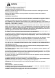
Warning: do not place any pot or pan on the open oven door. The door is made of glass and it can break if loaded with a weight. Warning: this appliance must be used only with base feet properly installed. See installation instruction for details. Installation instructions This appliance shall only be installed by an authorized person.
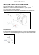
INSTALLATION MANUAL ANTI-TIP STABILlTY DEVICE INSTALLATION INSTRUCTIONS 1. The anti-tip bracket have to be installed to the rear wall as shown. The height for the bracket location from the floor has to be determined after the range legs have been adjusted to the proper installation height - as shown in the installation instructions – and after the range has been leveled. 2. Measure from the floor to the bottom of the anti-tip bracket location on the back of the range. 3.
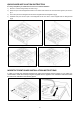
BACKGUARD INSTALLATION INSTRUCTION It’s always compulsory to installa the riser even for an island installation 1) Remove n°2 screws fixing worktop as shown in fig.1 2) Place front part of the backguard and attach it from bottom side with the two removed screws (point 2) as shown in fig .2 3) Fix the front part of the backguard with the screws supplied with the backguard kit (fig.3) 4) Assemble back part with front part of the backguard and fix them with a screws supplied with the backguard kit (fig.
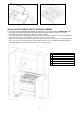
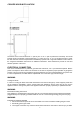
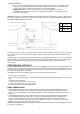
INSTALLATION SIDE-BY-SIDE TO KITCHEN CABINET 1. This range may be installed directly adjacent to existing 36" (91.5 cm) high cabinets. IMPORTANT: The top border of the worktop should be at the same level of the adjacent cabinet countertop. This can be accomplished by raising the unit using the adjustment spindles on the legs. 2. The range CANNOT be installed directly adjacent to sidewalls, tall cabinets, tall appliances, or other vertical surfaces above 36" (91.4 cm) high.
COOKER HOOD INSTALLATION The bottom of the hood should be 25 1/2" (65 cm) min. to 31 1/2" (80 cm) above the countertop. This would typically result in the bottom of the hood being 61 1/2" (156.2 cm) to 67 1/2" (171.5 cm) above the floor. Check for other minimum clearance requirements mandated by specific local or regional installation codes. Refer to the rangehood installation instructions for additional information. These dimensions provide for safe and efficient operation of the hood.
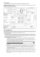
Wiring diagram For freestanding gas range model X304GGVX M7S0GTU4X(2 or 5)A CAUTION: label all wires prior to disconnection when servicing controls. Wiring errors can cause improper and dangerous operation. Verify proper operation after servicing. GAS CONNECTION All gas connections must be made according to national and local codes. The gas supply (service) line must be the same size or greater than the inlet line of the appliance. This range uses a 1/2" NPT inlet (see fig.
3. Flexible Connections: a) If the unit is to be installed with flexible couplings and/or quick disconnect fittings, the installer must use a heavy-duty, AGA design-certified commerciai flexible connector of at least 1/2" (1.3 cm) ID NPT (with suitable strain reliefs) in compliance with ANSI Z21.41 and Z21.69 standards. b) In Massachusetts: The unit must be installed with a 36" (3-foot) long flexible gas connector. c) In Canada: CAN 1-6.10-88 metal connectors for gas appliances and CAN 1-6.
REPLACEMENT PARTS Only authorized replacement parts may be used in performing service on the appliance. Replacement parts are available from factory authorized parts distributors. Conversion to different types of gas Before carrying out any maintenance work, disconnect the appliance from the gas and electric supply. For LP Gas fit regulator assembly described in Fig.
Fig. 9A Fig. 10 Fig. 9B Fig. 11 Follow the instructions below to change the broiler burner nozzle: 1) Loosen the screw and pull out the burner from the support being careful not to damage the ignition plug and the thermocouple (Fig. 12). 2) Unscrew the nozzle C (Fig. 12) using a 7 mm spanner and replace it with the nozzle needed for the new type of gas according to what is indicated in TABLE shown below. Fig.
Models X304GGVX [M7S0GTU4X (2 or 5)A] Adapting to different types of gas CAUTION: save the orifices removed from the appliance for future use Burner Position Auxiliary Rear L Semi-Rapid Front R Rapid Rear R Front L Inner Dual Burner Front L Outer Oven Broiler Oven downside Oven upside Injector diam. [mm.
SERVICE & MAINTENANCE INSTRUCTIONS Service and maintenance only to be carried out by an authorised person To replace parts such as burners, valves and electric components, the appliance must be open removing the worktop. Note: if the valves must be replaced, first disassemble the ignitions switches wires. It is recommended to replace the valve gaskets each time the valve is replaced, thus ensuring a perfect seal between the body and the gas train.
USER MANUAL WARNINGS: Do not to cover the holes inside the oven with aluminium paper Do not to cover the burners of cooktop with aluminium paper Do not store any flammable objects or objects under pressure in the storage compartment Keeping appliance area clear and free from combustible materials, gasoline and other flammable vapors and liquid. Do not store dangerous or flammable material in the cabinet areas above appliance; store them in a safe place in order to avoid potential hazards.
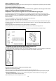
CONTROL PANEL DESCRIPTION On the control panel, small symbols show the function of each knob or key. Here as follows are the several controls that a cooker can have: the symbol shows the disposition of burners on the worktop, the full dot identifies the burner in object (in this case the front burner on the right).
WARNING: check the position of the burner caps before operation. Correct usage of pans: - Dry the bottom of the pan before placing it on the hotplate. - Use pots with a flat, thick bottom, except for wok cooking. - When using the burners, ensure that the handles of the pans are correctly positioned. Keep children away from the appliance. - When cooking foods with oil and fat, which are very flammable, the user should not leave the appliance unattended.
The ignition device should not be used for more than 15 seconds. If after that period the burner still has not been lit, do not use the device and open the door of the room or wait at least 60 seconds before trying to light the oven again. WARNING: when trying to light the oven, the door must always be open.
To activate the convection fan use the selector placed on control panel. Turn the knob anti clockwise for activation of the convection fan +light Turn the knob clockwise to turn on the oven light.
Note: The use of a gas cooking appliance produces heat and humidity in the room where it is installed. Therefore, proper ventilation in the room is needed and natural ventilation openings must remain unobstructed and activating the mechanical exhaust fan/range hood. Intensive and continuous use of the appliance may require additional ventilation, for example by opening a window, or increasing the power of the mechanical exhaust fan/range hood, if installed.
X304GGVBI X304GGVRO DESCRIPTION BURNERS FLASK PART FOR DUAL WOK AND SEMI RAPID BURNERS THERMOSTAT CLIP WORKTOP FRONTGUARD COVER FOR SMALL FLAME SPREADER COVER FOR MEDIUM BURNER COVER FOR RAPID BURNER COVER IN FOR DUAL BURNER FLAME SPREADER COVER OUT FOR DUAL BURNER FLAME SPREADER UP SUPPORT FOR AXIAL COOLIN FAN DOWN SUPPORT FOR AXIAL COOLIN FAN INSIDE FLAP DOOR PROTECTION FOR FAN ASSISTED OVEN BLACK OVEN DRIP TRAY DISHWARMER BOTTOM BRIDLE FOR FIXING GAS VALVES PROFILE FOR GLASS DOOR PROFILE FOR GLASS DOOR
886 917 917 917 917 917 929 930 940 943 947 964 965 972 1041 1043 1044 1046 1047 1143 1406 1407 1411 1415 1419 1421 1508 1508 1508 1508 1508 1602 1603 1608 1609 1614 1615 1617 1622 1624 1627 1628 1631 1639 1644 1645 1646 1685 1686 1687 1705 1801 1803 1804 2016 2017 2031 2032 2057 2097 2098 2099 4106 4301 4301 4301 4301 4301 4302 4302 4302 4302 4302 5140 502180 200327 125003 125027 125033 125045 202389 202214 201168 308035 403343 408068 408063 202360 401904 401905 401906 401961 401962 910711 403435 406396 4