
Specifications


CC
1100E
SWRS
082
Page
29
of
92
expects
a header byte
with
the
burst bit set to
zero and one data byte. After the data byte
,
a
new
header byte
is expected; hence, CSn can
remain low. The burst access method expects
one
header
byte and then consecutive data
bytes until terminating
the access by setting
CSn high.
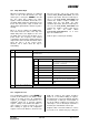
The following header bytes access the FIFOs:
0x3F: Single byte access to TX FIFO
0x7F: Burst access to TX FIFO
0xBF: Single byte access to RX FIFO
0xFF: Burst access to RX FIFO
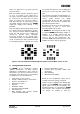
When writing to the TX FIFO, the status byte
(see
Section
10.1
) is output
on
SO
for each
new data byte as shown in
Figure
11
. This
status byte can be used to detect TX FIFO
underflow while writing data to the TX FIFO.
Note that th
e status byte contains the number
of bytes free
before
writing the byte in
progress to the TX F
IFO. When the last byte
that fits in the TX FIFO is transmitted
on
SI,
the status byte received concurrently on SO
will indicate that one byte is free in the TX
FIFO.
The
TX
FIFO may be flushed by issuing a
SFTX
command strobe. Similarly, a
SFRX
command strobe will flush the
RX
FIFO.
A
SFTX
or
SFRX
command strob
e can only be
issued in the IDLE, TXFIFO_UNDER
F
LOW
,
or
RXFIFO_OVERFLOW state
s
. Both FIFOs are
flushed when going to the SLEEP state.
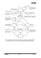
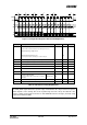
Figure
13
gives a brief overview of
different
register
access types possible.
10.6
P
ATABLE Access
The 0x3E address is used to access the
PATABLE
, which is used for selecting PA
power control settings. The SPI expects up to
eight data bytes after receiving the address.
By programming the
PATABLE
, controlled PA
power ramp
-
up and ramp
-
down can be
achieved, as well as ASK modulation shaping
for reduced bandwidth.
See
SmartRF
®
Studio
[8]
for recommended shaping
/ PA ramping
se
quence
s
.
See
also
S
ection
24
on page
52
for
details on output power programming
.
The
PATABLE
is an 8
-
byte
table
that defines
the PA control settin
gs to use for each of the
eight PA power values (selected by the 3
-
bit
value
FREND0.PA_POWER
). The
table
is
written and read from the lowest setting (0) to
the highest (7), one byte at a time. An index
counter is used to control t
he access to the
table
. This counter is incremented each time a
byte is read or written to the
table
, and set to
the lowest index when
CSn
is high. When the
highest value is reached the counter restarts
at zero.
The access to the
PATABLE
is either single
byte or burst access depending on the burst
bit. When using burst access the index counter
will count up; when reaching 7 the counter will
restart at 0.
The
R/
W;¯
bit controls whether the
access is a
read or a
write access.
If one byte is written to the
PATABLE
and this
value is to be read out
,
CSn
must be set high
before the read access in order to set the
index counter back to zero.
Note that the content of the
PATABLE
is lost
when entering the SLEEP state, except for the
first byte (index 0).
Please referr to Design Note DN501
[17]
for
more information
Figure
13
: Register Access T
ypes