D:\manual\UM_PCM-ULT\ML_Ult3k\661-UT3K-002-31.
D:\manual\UM_PCM-ULT\ML_Ult3k\661-UT3K-002-31.doc IMPORTANT SAFETY INSTRUCTIONS IMPORTANT SAFETY INSTRUCTIONS SAVE THESE INSTRUCTIONS ●WARNING (Controlled Environment) : Intend for installation in a controlled environment. ●WARNING (Fuses): To reduce the risk of fire, replace only with the same type and rating of fuse. ●CAUTION (Live Heat Sink): Risk of electric shock-Heat sink is live. Disconnect unit before servicing.
D:\manual\UM_PCM-ULT\ML_Ult3k\661-UT3K-002-31.doc TABLE OF CONTENTS IMPORTANT SAFETY INSTRUCTIONS…………………………………...………………………..………i TABLE OF CONTENTS…………………………………..……………………………………………….ii INTRODUCTION…………………………………………………………………………...…………..iii 1. P R E S E N T A T I O N ………… ……...………….……………………,.………………………2 FRONT PANEL REAR PANEL OUTPUT 2. INSTALLATION………………………………………………………………………………………8 3. OPERATION……………………………………………………………………..……………………9 4. ALARMS………………………….….…………………………………………..…………………10 5. SOFTWARE OPTIONS 6.
D:\manual\UM_PCM-ULT\ML_Ult3k\661-UT3K-002-31.doc INTRODUCTION SAVE THESE INSTRUCTIONS Please read and save this manual! Thank you for selecting this uninterruptible power system (UPS). It provides you with a perfect protection for connected equipment. The manual is a guide to install and use the UPS. It includes important safety instructions for operation and correct installation of the UPS. If you should have any problems with the UPS, please refer to this manual before calling customer service.
D:\manual\UM_PCM-ULT\ML_Ult3k\661-UT3K-002-31.doc Advanced monitoring software The on-line UPS and UPS-MON series monitoring software (optional kits) make your computer operate intelligent and provide you with the ability of perfect protection of your critical devices. The software is available for most operation systems and is supplied with a communication cable that connects to the UPS. Note: There is no guarantee that interference to radio/TV will not occur in a particular installation.
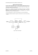
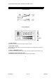
D:\manual\UM_PCM-ULT\ML_Ult3k\661-UT3K-002-31.doc 1. PRESENTATION Front LED Panel INVERTER Front LCD Panel 1.1 “LINE” indicator The indicator illuminates when the line input voltage is normal. 1.2 “BY PASS” indicator The indicator illuminates when the loads are supplied from the utility power, through the by-pass direction. 1.3 “INV” or “INVERTER” indicator The indicator illuminates when the output power of UPS is supplied from the inverter circuit. 1.
D:\manual\UM_PCM-ULT\ML_Ult3k\661-UT3K-002-31.doc 1.5 “FAULT” indicator It shows something wrong concerning about the UPS. 1.6 “ON” button With the UPS plugged in, press the “ON” button to turn on the UPS and power the loads. “ON” also activates the UPS‘s self-test and utility line voltage displays. 1.7 “OFF” button Press the OFF button to turn off the UPS and the loads. 1.8 “SELECT” button (LCD Panel only) The relevant value appears on the upper screen. There are four display modes can be selected.
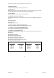
D:\manual\UM_PCM-ULT\ML_Ult3k\661-UT3K-002-31.doc Rear Panel (Tower type) OUTPUT VOLTAGE MODE ALIGNMENT OUTPUT VOLTAGE MODE ALIGNMENT RS-232 INTERFACE RS-232 INTERFACE EXT. BATTERY EXT. BATTERY OUTLET INLET OUTLET INLET CIRCUIT BREAKER CIRCUIT BREAKER 1500VA 700VA/1000VA RS-232 INTERFACE EXT. BATTERY RS-232 INTERFACE EXT.
D:\manual\UM_PCM-ULT\ML_Ult3k\661-UT3K-002-31.doc Rear Panel (Rack-Mount type) FRONT VIEW REAR VIEW OUTLET CIRCUIT BREAKER OUTPUT VOLTAGE MODE ALIGNMENT RS-232 INTERFACE EXT. BATTERY INLET 700VA / 1000VA RM OUTLET CIRCUIT BREAKER OUTPUT VOLTAGE MODE ALIGNMENT RS-232 INTERFACE EXT.
D:\manual\UM_PCM-ULT\ML_Ult3k\661-UT3K-002-31.doc Rear Panel (Rack-Mount type) REAR VIEW REAR VIEW OUTPUT VOLTAGE MODE ALIGNMENT RS-232 INTERFACE TERMINAL BLOCK CIRCUIT BREAKER EXT. BATTERY 100 / 110 / 115 / 120V SYSTEM 2K / 3K RM OUTPUT VOLTAGE MODE ALIGNMENT RS-232 INTERFACE CIRCUIT BREAKER INPUT EXT.
D:\manual\UM_PCM-ULT\ML_Ult3k\661-UT3K-002-31.doc 1.12 EXTERNAL BATTERY PACK CONNECTOR (optional) Batteries: Can be connected with external battery pack. CAUTION: Use only factory supplied or authorized connecting cable for external battery! 1.13 SNMP INTERFACE PORT (optional) Provide the SNMP adapters for 10-BaseT Ethernet and Token Ring connectors.
D:\manual\UM_PCM-ULT\ML_Ult3k\661-UT3K-002-31.doc 2. INSTALLATION Inspect the UPS upon receipt. The packaging is recyclable; keep it for reuse or be disposed of properly. 2.1 Placement Install the UPS in a protected area with adequate flowing air and free of excessive dust. Do not operate the UPS where the temperature and humidity is out of the specified limits. 2.
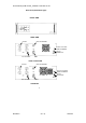
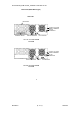
D:\manual\UM_PCM-ULT\ML_Ult3k\661-UT3K-002-31.doc 2.7 Installations with accessories of “Vertical” and “Wall-mounted” types: Please install the vertical and wall-mounted types of units according to the following illustration. Vertical Installation Wall-mounted installation.
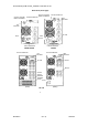
D:\manual\UM_PCM-ULT\ML_Ult3k\661-UT3K-002-31.doc 2.8 Installation with accessories of “Rack-mounted” types: Please install the types of units according to the following illustration. Installation with bottom bracket. Part No: RMB-06, 2 PCS. Screw: M5*11, 4 PCS. Installation with rear bracket Part No: RMB-01, 2PCS. Screw: M5*11, 4 PCS.
D:\manual\UM_PCM-ULT\ML_Ult3k\661-UT3K-002-31.doc 2.9 Installation with accessories of “Stack” types: Please install the types of units according to the following illustration.
D:\manual\UM_PCM-ULT\ML_Ult3k\661-UT3K-002-31.doc 3. OPERATION 3.1 Switch on While utility input is connected to the UPS, turn on the input circuit breaker and press the "ON" button and keep pressing over than 0.5 second. After that, connect the electrical cords of the equipment that is going to be used such as computer or monitor with the terminal on the rear panel of UPS. Don't overload the machine with all the equipment used. The buzzer will beep continuously to indicate overload status.
D:\manual\UM_PCM-ULT\ML_Ult3k\661-UT3K-002-31.doc 4. ALARM 4.1 “BACKUP”(slow alarm) When the UPS is working under “BACKUP” mode, the UPS would emit audible alarm. The alarm stops when the UPS is return to “LINE” mode operation. Anyone can stop the alarm by press the “ON” button during backup mode. Attention: The alarm of “BACKUP” is going to beep every four seconds. (Slow-speed beep). Attention: The UPS provides mute function for the warning.
D:\manual\UM_PCM-ULT\ML_Ult3k\661-UT3K-002-31.doc 5. SOFTWARE OPTIONS AND COMPUTER INTERFACE PORT 5.1 Power Monitoring Software The UPS-MON series software (or other power monitoring software) is applied standard RS-232 interface to perform monitoring functions, and then provides an orderly shutdown of a computer in the event of power failure. Moreover, UPS-MON displays all the diagnostic symptoms on monitor, such as Voltage, Frequency, Battery level and so on. The software is available for DOS, Windows 3.
D:\manual\UM_PCM-ULT\ML_Ult3k\661-UT3K-002-31.doc 5.4 The pin of computer interface port The pin of computer interface port has the following characteristics: 5.4.1. Pin 5 and 2 are open collector outputs that must be pulled up to a common referenced supply no greater than DC +40V. The transistors are capable of a maximum nonconductive load of DC 50 mA, Use only pin 7 as the common. 5.4.2. Pin 5 generates a High to Low signal when the battery inside the UPS has less than 5 minutes back up time left. 5.4.3.
D:\manual\UM_PCM-ULT\ML_Ult3k\661-UT3K-002-31.doc 6. MAINTENANCE AND STORAGE 6.1 Maintenance 6.1.1. 6.1.2. 6.1.3. 6.1.4. 6.1.5. Keep the unit clean and vacuum the ventilation intake periodically. Wipe with soft loose and damp cloth. Check for loose and bad connections monthly. Never leave the unit on an uneven surface. Position the unit to allow at least 10 cm clearance between the rear panel and the wall. Keep the ventilation intake open. 6.1.6. Avoid direct sunlight, rain and high humidity. 6.1.7.
D:\manual\UM_PCM-ULT\ML_Ult3k\661-UT3K-002-31.doc 7. BATTERY REPLACEMENT AND BATTERY PACK INSTALLATION 7.1 Battery’s life of UPS The battery’s life of UPS is about 3-6 years under normal usage. 7.2 Battery Replacement See figure. UPS and external battery pack. Once the UPS’s battery is no longer useful and must be replaced. Please follow the instructions for easy battery replacement. 7.2.1. Unplug unit from AC power source and disconnect all connected equipment. 7.2.2. Disconnect AC power cord from UPS. 7.
D:\manual\UM_PCM-ULT\ML_Ult3k\661-UT3K-002-31.doc APPENDIX A TROUBLESHOOTING Problems 1. UPS can't operate after pressing On/Off switches 2.
D:\manual\UM_PCM-ULT\ML_Ult3k\661-UT3K-002-31.doc APPENDIX B SPECIFICATIONS Tower model 19" rack-mount model Power Rating P.F.=0.7 AC Input Battery AC output Efficiency Transfer Noise Level LED Indicators Alarm 700VA 1000VA 1500VA 2000VA 3000VA 700VA RM 1000VA RM 1500VA RM 2000VA RM 3000VA RM 700VA 1KVA 1.5KVA 2KVA 3KVA 490W 700W 1050W 1400W 2100W Voltage 100V:76V-130V 110V:80V-138V 115V:83.
D:\manual\UM_PCM-ULT\ML_Ult3k\661-UT3K-002-31.