
User`s manual

D:\manual\UM_PCM-ULT\ML_Ult3k\661-UT3K-002-31.doc
KEVIN KU 第 19 頁 2003/3/4
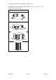
5.4 The pin of computer interface port
The pin of computer interface port has the following characteristics:
5.4.1. Pin 5 and 2 are open collector outputs that must be pulled up to a common
referenced supply no greater than DC +40V. The transistors are capable of a
maximum nonconductive load of DC 50 mA, Use only pin 7 as the common.
5.4.2. Pin 5 generates a High to Low signal when the battery inside the UPS has less than
5 minutes back up time left.
5.4.3. Pin 2 generates a High to Low signal when the line is fail.
5.4.4. The UPS will shut down when a high RS-232 level is sustained on pin 6 for 0.36
seconds.
5.4.5. Pin 9 is also the RS-232 data output.
5.4.6. Pin 6 is RS-232 data input (RxD)
NOTE:
1. Switch rating +40V, 0.15A non-inductive.
2. Pin 7 should be connected to ground only.
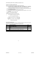
Communicating Interface Port
We provide a standard RS232 line (that is compatible with DB9 line) socket on the rear panel
of UPS. That port possesses several signals as explained below:
Pin# Function Explanation I/O
2 Power Fail-normally open status, will become closed during active OUTPUT
4 Reference GND for pin2,5 OUTPUT
5 Battery Low- normally open status, will become closed during
active
OUTPUT
6 Remote shutdown UPS-keep this pin at high voltage(+5V~+12V)
500ms to shutdown UPS. Activates at battery mode
INPUT
7 Reference GND for pin6 INPUT
15