
User`s manual


D:\manual\UM_PCM-ULT\ML_Ult3k\661-UT3K-002-31.doc
KEVIN KU 第 7 頁 2003/3/4
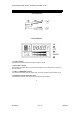
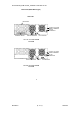
1.5 “FAULT” indicator
It shows something wrong concerning about the UPS.
1.6 “ON” button
With the UPS plugged in, press the “ON” button to turn on the UPS and power the loads.
“ON” also activates the UPS‘s self-test and utility line voltage displays.
1.7 “OFF” button
Press the OFF button to turn off the UPS and the loads.
1.8 “SELECT” button (LCD Panel only)
The relevant value appears on the upper screen. There are four display modes can be
selected.
Output voltage display
Input voltage display
Input frequency
Temperature inside the UPS
1.9 “BATT” bar graph (RECTANGLE INDICATOR)
The rectangle indicator shows the percentage of battery capacity.
1.10 “LOAD” bar graph (RECTANGLE INDICATOR)
The indicator shows the power being drawn by the load.
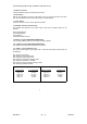
1.11 “FAULT” codes (LCD Panel only)
The relevant value appears at the upper screen. There are seven kinds of fault modes can
be displayed.
E01: Warning of fail output
E02: Warning of wrong temperature
E03: Warning of output short circuit
E04: Warning of overload (exceeding 150%)
E05: Warning of mistaken +/- DC Bus
E06: Warning of wrong electrical charging voltage
E07: Warning of batteries mistake
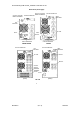
Load Indicator
Light no.5
Light no.4
Light no.3
Light no.2
Light no.1
% of Load Value
over 96%
76-95 %
51-75 %
26-50 %
10-25 %
Battery Indicator
Light no.5
Light no.4
Light no.3
Light no.2
Light no.1
% of Bat Level
over 91 %
76-90 %
51-75 %
26-50%
0-25%
3