
Installation Guide


10
13. CONNECT WIRING (ALL BLOWERS)
Position the power pack below the installed custom hood.
WARNING
!
Risk of electric shock. Electrical wiring must be done by qualified personnel in accordance with all applicable
codes and standards. Before connecting wires, switch power off at service panel and lock service disconnecting
means to prevent power from being switched on accidentally.
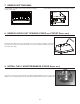
INTERNAL BLOWERS: Insert the house wiring cable through the wire clamp
previously installed in step 8. Tighten the wire clamp to
secure the cable. Connect cable into wiring box using
wire connectors. Connect BLACK to BLACK, WHITE to
WHITE and GREEN or bare wire under GREEN ground
screw. DO NOT FORGET TO CONNECT THE GROUND.
Reinstall wiring box cover.
IN-LINE OR EXTERIOR BLOWERS: See instructions included with blower.
HE0059
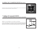
Refer to the instructions included with the selected blower/rough-in kit (sold
separately) for details on installing the rough-in plate. Install the rough-in plate so
that the wiring box is located on the right side when facing the hood, as specified
on the blower housing label.
12. INSTALL THE ROUGH-IN PLATE FOR EXTERNAL BLOWER
(CP57E SERIES ONLY)
HD0522
WIRING BOX
COVER
LOCK NUTS
14. INSTALL POWER PACK
CAUTION
Take care not to kink ducting when installing the power pack.
Using provided no. 8 x 1/2” chrome plated screws, install the power pack inside the
custom hood. Start with 2 screws on front corners, then use 4 screws for sides and use
the remaining screws to finalize securing the front power pack. (See figure at right for
mounting screw specific locations.)
Make sure the adapter/damper (or the adapter) enters the ducting. When there is
access to the top of the power pack, seal connections with metal foil duct tape.
HH0102A
MODEL CP55IQ ONLY: If the model CP55IQ is to be installed with a non-duct kit, install a 8” to 7” reducer (included in non-duct kit) prior
to install the power pack in its custom hood.