
Installation Guide


6
2. PREPARE INSTALLATION
WARNING
!
When performing installation, servicing or cleaning the unit, it is recommended to wear safety glasses and gloves.
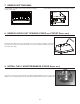
NOTE: Before proceeding to the installation, check the contents of the box. If items are missing or damaged, contact the manufacturer.
Make sure that the following items are included:
- Power Pack
- Accessories • Hybrid baffle filters with handles (3 for 36’’ width power pack, 4 for 42’’ width power pack and 5 for 48” to 66” width power
packs)
• 8” round adapter and damper (included with CP55IQ power pack series)
• 10” round in-line vertical damper (included with CP57IQT power pack series)
• 10” round adapter (included with CP57IQT power pack series)
• Bag of parts including: 1 wire clamp, 2 wire connectors, 4 no. 8 x 3/8” screws, 9 no. 8 x 1/2” chrome plated screws,
10 no. 8-32 x 1/4” screws (not used with this product, please discard).
Parts sold separately:
• ACR Series remote control kit
• In-line blower assembly model ILB3, ILB6, ILB9 or ILB11.
• Exterior blower assembly model EB6, EB9, EB12 or EB15.
• Ducts, elbows, wall and roof caps. Refer to page 3 and 4 for a complete list of venting options and model numbers.
• Non-duct kit ANKCP55 Series, mandatory for non-ducted installation.
NOTE: During installation, protect countertop and/or cooktop.
3. CUSTOM HOOD PREPARATION
WARNING
!
When building a custom hood, always follow all applicable construction codes and standards.
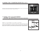
The custom hood must be constructed to fit the size and shape of the CP55IQ, CP57IQT or the CP57E power pack.
See chart and illustration for details.
POWER PACK TOTAL
WEIGHT
POWER PACK DIMENSIONS
MODEL WIDTH A* B* C
CP55IQ
36” 52 LB.19
5
⁄16”34
7
⁄16” 4¼”
42” 62 LB.19
5
⁄16”40
7
⁄16”4
3
⁄8”
CP57IQT
36” 62 LB.19
5
⁄16”34
7
⁄16”5
3
⁄8”
48” 72 LB.19
5
⁄16”46
7
⁄16”5
3
⁄8”
48” 72 LB.22
9
⁄16”46
7
⁄16”5
3
⁄8”
54” 82 LB.22
9
⁄16”52
7
⁄16”5
3
⁄8”
60” 85 LB.22
9
⁄16”58
7
⁄16”5
3
⁄8”
66” 88 LB.22
9
⁄16”64
7
⁄16”5
3
⁄8”
CP57E
36” 40 LB.22
9
⁄16”34
7
⁄16”6”
48” 53
LB.22
9
⁄16”46
7
⁄16”6”
60” 66 LB.22
9
⁄16”58
7
⁄16”6”
A
B
C
7/8
”
4½”
HD0296A
C
L
12”
3”
REAR
FRONT
* Dimensions A and B include rivets head.
To minimize the gap around the power pack, take actual width and depth measurements of power pack and add 1/16” to get D and E
measurements. Cut the hole in the bottom of the cabinet according to dimensions. See chart and illustration for details.
POWER PACK CUTOUT DIMENSIONS
MODEL WIDTH DE
CP55IQ
36” 19
3
⁄8” 34½”
42” 19
3
⁄8” 40½”
CP57IQT
36” 19
3
⁄8” 34½”
48” 19
3
⁄8” 46½”
48” 22
5
⁄8” 46½”
54” 22
5
⁄8” 52½”
60” 22
5
⁄8” 58½”
66” 22
5
⁄8” 64½”
CP57E
36” 22
5
⁄8” 34½”
48” 22
5
⁄8” 46½”
60” 22
5
⁄8” 58½”
E
HD0367
D