INSTALLATION INSTRUCTIONS HB0132 CP55IQ, CP57IQT AND CP57E SERIES ! INTENDED FOR DOMESTIC COOKING ONLY ! READ AND SAVE THESE INSTRUCTIONS INSTALLER: LEAVE THIS MANUAL WITH HOMEOWNER. HOMEOWNER: USE AND CARE INFORMATION ON PAGES 12 TO 14. BEST; Hartford, Wisconsin www.BestRangeHoods.com 800-558-1711 BEST; Drummondville, QC, Canada www.BestRangeHoods.com 866-737-7770 To register your product online or for additional information visit www.BestRangeHoods.com SV21422 rev.
! WARNING CAUTION 1. For indoor use only. 2. For general ventilating use only. Do not use to exhaust hazardous or explosive materials and vapors. 3. To avoid motor bearing damage and noisy and/or unbalanced impellers, keep drywall spray, construction dust, etc. off power unit. 4. Your power pack motor has a thermal overload which will automatically shut off the motor if it becomes overheated. The motor will restart when it cools down.
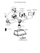
- CP55IQ AND CP57IQT POWER PACK SYSTEMS - MODEL 634 OR 644 (ROOF CAP) MODEL 643 (8” ROUND WALL CAP) MODEL 437 (HIGH CAPACITY ROOF CAP) MODEL 441 (10’’ ROUND WALL CAP) MODEL 418 (10” ROUND ADJUSTABLE ELBOW) 8” ROUND ADJUSTABLE ELBOW 8” ROUND MODEL 410 (10” ROUND DUCT — 2 FT.
- CP57E POWER PACK SYSTEM - MODEL 437 (HIGH CAPACITY ROOF CAP) MODEL ILB9 (800 CFM) OR ILB11 (1100 CFM) IN-LINE BLOWER (INCLUDES TWO 8” X 12” TO 10’’ ROUND TRANSITIONS) MODEL EB6 (600 CFM) OR EB9 (900 CFM) EXTERIOR BLOWER MODEL 441 (10” ROUND WALL CAP) MODEL 643 (8” ROUND WALL CAP) MODEL ILB6 (600 CFM) IN-LINE BLOWER (INCLUDES TWO 4½” X 18½” TO 10’’ ROUND TRANSITIONS) MODEL 418 (10” ROUND ADJUSTABLE ELBOW)— OPTIONAL MODEL ILB3 (280 CFM) IN-LINE BLOWER (INCLUDES ONE 8” TO 10” ROUND TRANSITION) + -
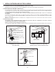
1. INSTALL DUCTWORK AND ELECTRICAL WIRING 1.1 NON-DUCTED INSTALLATION (CP55IQ SERIES POWER PACKS ONLY) CP55IQ Series power packs may be non-ducted. ANKCP55 non-duct kit must be installed (sold separately). 1.2 DUCTED INSTALLATION (ALL POWER PACKS) For a CP57E Series power pack, either an exterior blower or in-line blower must be used. The CP57E Series power pack must be installed with blower models ILB3, ILB6, ILB9, ILB11, EB6, EB9, EB12 or EB15 only.
2. PREPARE INSTALLATION ! WARNING When performing installation, servicing or cleaning the unit, it is recommended to wear safety glasses and gloves. NOTE: Before proceeding to the installation, check the contents of the box. If items are missing or damaged, contact the manufacturer.
4. MOUNT CUSTOM HOOD INTERNAL FRAMEWORK ! WARNING The wood hood must be positively secured to wall studs or other wooden framework behind the drywall. Make sure it is capable of supporting its own weight and the weight of the CP55IQ, CP57IQT or CP57E. Failure to do so may cause personal injury or damage to countertop or cooktop. The CP55IQ, CP57IQT and CP57E power pack is supported by the custom hood internal framework with screws provided in parts bag.
. REMOVE KNOCK-OUT OPENING (CP55IQ AND CP57IQT SERIES ONLY) From inside the power pack, remove the wiring box cover by removing 2 retaining screws and set aside. Punch out the electrical knockout hole on top of the power pack. Install the wire clamp (included in parts bag). HR0027 9. INSTALL THE 8” ADAPTER/DAMPER (CP55IQ SERIES ONLY) MOUNTING SCREW LOCATIONS Using 4 no. 8 x 3/8” screws from parts bag, assemble the adapter/damper on the top of the power pack.
12. INSTALL THE ROUGH-IN PLATE FOR EXTERNAL BLOWER (CP57E SERIES ONLY) Refer to the instructions included with the selected blower/rough-in kit (sold separately) for details on installing the rough-in plate. Install the rough-in plate so that the wiring box is located on the right side when facing the hood, as specified on the blower housing label. WIRING BOX COVER LOCK NUTS HD0522 13. CONNECT WIRING (ALL BLOWERS) ! WARNING Risk of electric shock.
15. PERFORM THE EXTERNAL BLOWER CONNECTIONS (CP57E SERIES ONLY) ! WARNING Do not plug the two cords together. To install the blower see instructions included with the blower. Plug the 3-prong plug cord from rough-in plate to the 3-prong male connector inside the power pack (A) and the 2-prong male connector cord from rough-in plate to the 2-prong plug inside the power pack (B). B A HE0078 16.
18. REINSTALL HYBRID BAFFLE FILTERS CAUTION Remove protective plastic film covering hybrid baffle filters before installing them. It is recommended to install side filters first and finish with center one(s). 1 2 1. Insert one end of hybrid baffle filter into the front channel of the power pack. 2. Raise the other end toward the inside of power pack and insert in the grease drip rail of the power pack. HD0526 19.
20. LIGHTING This power pack is equipped with LED lamps which require no maintenance. ! WARNING Do not touch lamps during or soon after operation. Burns may occur. 21. USE AND CARE Hybrid Baffle Filters The hybrid baffle filters should be cleaned frequently. Use a warm detergent solution. Wash more often if your cooking style generates greater grease — like frying foods or wok cooking. Remove hybrid baffle filters by pushing them towards the back of power pack and rotating filters downward.
22. OPERATION Always turn your blower on before you begin cooking to establish an airflow in the kitchen. Let the blower run for a few minutes to clear the air after you turn off the range. A) Blower delay-off button B) ON blower/Speed control button C) OFF blower/ Filter maintenance button D) OFF lighting E) ON lighting SPEED HC0016 1 2 A 3 4 B C D E A. BLOWER DELAY-OFF BUTTON: When blower is on, press the delay-off button to activate the delay-off function.
22. OPERATION (CONT’D) REMOTE CONTROL: 1 The power pack can also be operated using the optional ACR2 remote control. When a button is pressed on the remote control, it sends a coded signal to the receiver (factory installed on the power pack), indicating which function to activate. ¤ + 1 : : : : : Activates/deactivates delay-off. Decreases blower motor speed until turned OFF (4 to 3, 3 to 2, 2 to 1 and 1 to OFF). Turns blower motor ON and increases speed (OFF to 1, 1 to 2, 2 to 3, 3 to 4).
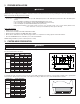
23. WIRING DIAGRAMS WARNING ! Risk of electrical shock. Electrical wiring must be done by qualified personnel in accordance with all applicable codes and standards. Before connecting wires, switch power off at service panel and lock service disconnecting means to prevent power from being switched on accidentally.
23. WIRING DIAGRAMS (CONT'D) WARNING ! Risk of electrical shock. Electrical wiring must be done by qualified personnel in accordance with all applicable codes and standards. Before connecting wires, switch power off at service panel and lock service disconnecting means to prevent power from being switched on accidentally. BLK M BLK HALL_2 BLDC2 3 2 1 HALL_1 MT_THM2 MT_THM1 WHT WHT Best CP57IQT Series (dual blower) M 3 2 1 LED DRIVER 4 3 2 1 1 CAL.
LINE NEUTRAL GROUND HE0169A 120 V AC J6 1 2 3 4 5 ~ ~ WHT + K2 K3 BLK Q1 - WHT ROUGH-IN PLATE GRN WHT BLK BLK - K1 ~ ~ + BLK WHT GRN K4 3 2 1 MED HIGH MED LOW LOW M BLK WHT J7 REF LOVAC LAMP RED GRY WHT BLK YEL WHT BLU ORG BLK WHT BRN 1 2 3 4 HIGH J1 5 MOTOR OUTPUT OUTPUT LED DRIVER WHT 0 BLK 120 ORG 120 BLU 88 PPL 60 PNK 45 YEL 10 WHT 0 WHT 0 BLK 120 ORG 120 BLU 88 PPL 60 PNK 45 YEL 10 WHT 0 INPUT LED LED BLK 1 2 3 4 5 6 7 8 9 1 2 3 4 5
24. SERVICE PARTS Best CP55IQ & CP57IQT Series 1 2 3 4 REPLACEMENT PARTS AND REPAIRS 14 6 5 13 7 12 8 11 10 9 In order to ensure your unit remains in good working condition, you must use Broan-NuTone genuine replacement parts only. Broan-NuTone genuine replacement parts are specially designed for each unit and are manufactured to comply with all the applicable certification standards and maintain a high standard of safety.
24. SERVICE PARTS (CONT'D) Best CP57E Series 1 2 REPLACEMENT PARTS AND REPAIRS 3 9 10 4 5 8 7 6 HL0212 KEY NO. 1 In order to ensure your unit remains in good working condition, you must use Broan-NuTone genuine replacement parts only. Broan-NuTone genuine replacement parts are specially designed for each unit and are manufactured to comply with all the applicable certification standards and maintain a high standard of safety.
25. WARRANTY ONE-YEAR LIMITED WARRANTY Broan-NuTone LLC (“Broan-NuTone”) warrants to the original consumer purchaser of its products that such products will be free from defects in materials or workmanship for a period of one year from the date of original purchase. THERE ARE NO OTHER WARRANTIES, EXPRESS OR IMPLIED, INCLUDING, BUT NOT LIMITED TO, IMPLIED WARRANTIES OF MERCHANTABILITY OR FITNESS FOR A PARTICULAR PURPOSE.
GUIDE D’INSTALLATION HB0132 SÉRIES CP55IQ, CP57IQT ET CP57E ! CONÇUES POUR USAGE DOMESTIQUE SEULEMENT ! LIRE ET CONSERVER CES DIRECTIVES INSTALLATEUR : LAISSER CE GUIDE AU PROPRIÉTAIRE. PROPRIÉTAIRE : DIRECTIVES D’UTILISATION ET D’ENTRETIEN EN PAGES 32 À 34. BEST; Hartford, Wisconsin www.BestRangeHoods.com 800 558-1711 BEST; Drummondville, QC, Canada www.BestRangeHoods.com 866 737-7770 Pour enregistrer votre produit en ligne ou pour obtenir plus d’information, veuillez consulter le www.BestRangeHoods.
! AVERTISSEMENT ATTENTION 1. Pour une utilisation à l’intérieur seulement. 2. Pour usage domestique seulement. Ne pas utiliser pour évacuer des vapeurs ou des matières dangereuses ou explosives. 3. Afin d’éviter tout dommage au moteur et de débalancer ou de rendre bruyante la roue du moteur, garder votre appareil à l’abri des poussières de gypse et de construction/rénovation, etc. 4.
- SYSTÈMES DE HOTTES ENCASTRABLES SÉRIES CP55IQ ET CP57IQT MODÈLE 634 OU 644 (CAPUCHON DE TOIT) MODÈLE 437 (CAPUCHON DE TOIT À HAUT RENDEMENT) MODÈLE 643 (CAPUCHON MURAL 8 PO ROND) MODÈLE 418 (COUDE AJUSTABLE DE 10 PO ROND) COUDE AJUSTABLE DE 8 PO ROND CONDUIT MODÈLE 410 (CONDUIT DE 10 PO ROND — SECTIONS DE 2 PI) STANDARD DE MODÈLE 441 (CAPUCHON MURAL 10 PO ROND) 8 PO ROND VOLET VERTICAL EN LIGNE DE 10 PO ROND (FOURNI AVEC ADAPTATEUR/VOLET 8 PO ROND (FOURNI AVEC LA HOTTE ENCASTRABLE À VENTILATE
- SYSTÈME DE HOTTE ENCASTRABLE SÉRIE CP57E MODÈLE 437 (CAPUCHON DE TOIT À HAUT RENDEMENT) VENTILATEUR EN LIGNE MODÈLE ILB9 (800 PCM) OU ILB11 (1100 PCM) (INCLUANT DEUX TRANSITIONS DE 8 PO X 12 PO À 10 PO ROND) VENTILATEUR EXTÉRIEUR MODÈLE EB6 (600 PCM) OU EB9 (900 PCM) MODÈLE 441 (CAPUCHON MURAL 10 PO ROND) MODÈLE 643 (CAPUCHON MURAL 8 PO ROND) VENTILATEUR EN LIGNE MODÈLE ILB6 (600 PCM) (INCLUANT DEUX TRANSITIONS DE 4½ PO X 18½ PO À 10 PO ROND) MODÈLE 418 (COUDE AJUSTABLE DE 10 PO ROND) — OPTIONNEL VEN
1. INSTALLER LES CONDUITS ET LE CÂBLAGE ÉLECTRIQUE 1.1 INSTALLATION EN RECIRCULATION (HOTTES ENCASTRABLES DE SÉRIE CP55IQ SEULEMENT) Les hottes encastrables de série CP55IQ peuvent être installées en recirculation. Le kit de recirculation ANKCP55 doit être installé (vendu séparément). 1.2 INSTALLATION AVEC CONDUITS (TOUTES LES HOTTES ENCASTRABLES) Pour les hottes encastrables de la série CP57E, un ventilateur en ligne ou extérieur doit être utilisé.
2. PRÉPARER L’INSTALLATION ! AVERTISSEMENT Il est recommandé de porter des lunettes et des gants de sécurité lors de l’installation, de l’entretien et de la réparation de cet appareil. NOTE : Avant de commencer l’installation, vérifier le contenu de la boîte. Si des pièces sont manquantes ou endommagées, contacter le manufacturier.
4. ASSEMBLAGE DE LA CHARPENTE DE L’ARMOIRE ! AVERTISSEMENT La charpente de bois doit être fixée solidement aux montants ou autre structure derrière la cloison. S’assurer qu’elle puisse supporter son propre poids en plus de celui de la CP55IQ, CP57IQT ou CP57E. Ne pas suivre cette directive peut entraîner des blessures corporelles ou des dommages à la surface de cuisson ou au comptoir de cuisine.
8. DÉFONCER L’OUVERTURE PRÉAMORCÉE (SÉRIES CP55IQ ET CP57IQT SEULEMENT) Par l’intérieur de la hotte encastrable, retirer le couvercle de la boîte de jonction en dévissant les 2 vis de retenue et les mettre de côté. Défoncer l’ouverture préamorcée pour le fil d’alimentation électrique située sur le dessus de la hotte encastrable. Installer le serre-fil (inclus dans le sac de pièces). HR0027 9.
12. INSTALLER LA PLAQUE VENTILATEUR POUR VENTILATEURS EXTERNES (SÉRIE CP57E SEULEMENT) Pour les détails concernant l’installation de la plaque ventilateur, voir les instructions comprises avec l’ensemble ventilateur et la plaque du ventilateur (vendu séparément). Installer la plaque ventilateur de façon à ce que la boîte de jonction se trouve à droite lorsque vous faites face à la hotte, tel qu’il est spécifié sur l’étiquette du ventilateur. COUVERCLE DE LA BOÎTE DE JONCTION ÉCROUS DENTELÉS HD0522 13.
15. BRANCHER LE VENTILATEUR EXTERNE (SÉRIE CP57E SEULEMENT) ! AVERTISSEMENT Ne jamais brancher ensemble le fil du ventilateur au fil d’alimentation de la hotte. Pour installer le ventilateur, voir les instructions comprises avec celui-ci. Brancher le fil du ventilateur à la prise à 2 alvéoles (B) et le fil d’alimentation électrique de la hotte encastrable (A) à la fiche à 3 broches, à l’intérieur de la hotte encastrable. B A HE0078 16.
18. RÉINSTALLER LES FILTRES À CHICANE HYBRIDES ATTENTION Avant d’installer les filtres à chicane hybrides, retirer le plastique protecteur de ceux-ci. Il est recommandé d’installer d’abord les filtres situés aux extrémités et de terminer par le(s) filtre(s) du centre. 1 2 1. Insérer une extrémité du filtre hybride dans le rail avant de la hotte. 2. Lever l’autre bout du filtre à l’intérieur de la hotte et l’insérer dans la gouttière. HD0526 19.
20. ÉCLAIRAGE L’éclairage de cette hotte encastrable est produit par des ampoules à DEL ne nécessitant aucun entretien. ! AVERTISSEMENT Ne pas toucher aux ampoules durant ou peu après leur utilisation. Peuvent causer des brûlures. 21. ENTRETIEN Filtres à chicane hybrides Les filtres à chicane hybrides doivent être nettoyés fréquemment. Utiliser une solution d’eau chaude et de détergent.
22. FONCTIONNEMENT Toujours mettre en marche le ventilateur avant de commencer la cuisson afin d’établir une circulation d’air dans la cuisine. Aussi, laisser le ventilateur fonctionner quelques minutes après l’arrêt de la cuisinière afin d’aérer. A) Bouton d’arrêt différé B) Bouton de mise en marche/ Vitesse du ventilateur C) Bouton d’arrêt du ventilateur/ Entretien des filtres D) Bouton d’arrêt d’éclairage E) Bouton d'activation d'éclairage VITESSE HC0016 1 A 2 3 4 B C D E A.
22. FONCTIONNEMENT (SUITE) TÉLÉCOMMANDE OPTIONNELLE : 1 La hotte encastrable peut également être contrôlée à l’aide de la télécommande optionnelle ACR2. Lorsqu’un bouton de la télécommande optionnelle est enfoncé, celui-ci envoie un signal codé au récepteur (installé en usine sur la hotte encastrable), indiquant quelle fonction doit être activée. ¤ + 1 : : : : : Active/désactive l’arrêt différé. Diminue la vitesse du moteur du ventilateur jusqu’à ARRÊT (4 à 3, 3 à 2, 2 à 1 et 1 à ARRÊT).
23. SCHÉMAS ÉLECTRIQUES AVERTISSEMENT ! Risque d’électrocution. Le raccordement électrique doit être effectué par du personnel qualifié conformément aux codes et aux standards. Avant d’effectuer le branchement, coupez l’alimentation électrique au panneau de distribution et verrouillez-le pour éviter une mise en marche accidentelle. BLDC TRA1 PRA1 M J7 1 2 R PRINCIPAL HE0168F RÉCEPTEUR RADIO 120 V C.A.
23. SCHÉMAS ÉLECTRIQUES (SUITE) AVERTISSEMENT ! Risque d’électrocution. Le raccordement électrique doit être effectué par du personnel qualifié conformément aux codes et aux standards. Avant d’effectuer le branchement, coupez l’alimentation électrique au panneau de distribution et verrouillez-le pour éviter une mise en marche accidentelle.
LA TERRE LIGNE NEUTRE MISE À HE0169F 120 V C.A. J6 1 2 3 4 5 N B ~ ~ + B K2 K3 B N Q1 - PLAQUE VENTILATEUR V N - K1 ~ ~ + 3 2 1 MOY. HAUTE MOY. BASSE BASSE LAMPE N B V M N B J7 REF B G BR 1 2 3 4 HAUTE J1 5 MOTEUR BASSE TENSION C.A.
24. PIÈCES DE REMPLACEMENT Séries CP55IQ et CP57IQT de Best 1 2 PIÈCES DE REMPLACEMENT ET SERVICE 3 4 Pour assurer le bon fonctionnement de votre appareil, vous devez toujours utiliser des pièces d’origine provenant de Broan-NuTone. Les pièces d’origine de Broan-NuTone sont spécialement conçues pour satisfaire toutes les normes de certification de sécurité applicables.
24. PIÈCES DE REMPLACEMENT (SUITE) Série CP57E de Best PIÈCES DE REMPLACEMENT ET SERVICE 1 2 3 9 10 4 5 8 7 6 HL0212 N° RÉF. 1 N° PIÈCE 7 8 9 10 * * SV05869 SV17871 SV17873 SV17875 SV61659 SV21414 SV21413 SV61639 SV61640 SV21412 SV20816 SV13923 SV13924 SV20825 SV21422 * SV08545 2 3 4 5 6 Pour assurer le bon fonctionnement de votre appareil, vous devez toujours utiliser des pièces d’origine provenant de Broan-NuTone.
25. GARANTIE GARANTIE LIMITÉE DE UN AN Broan-NuTone LLC (« Broan-NuTone ») garantit à l’acheteur consommateur initial de ses produits qu’ils sont exempts de tout défaut dans les matières premières ou la main-d’œuvre, pour une période de un an à compter de la date d’achat par le consommateur initial. IL N’Y A PAS D’AUTRES GARANTIES, EXPRIMÉES OU IMPLICITES, INCLUANT, MAIS NON LIMITÉES AUX GARANTIES IMPLICITES POUR FIN DE COMMERCIALISATION ET DE CONVENANCE DANS UN BUT PARTICULIER.
INSTRUCCIONES DE INSTALACIÓN HB0132 SERIES CP55IQ, CP57IQT Y CP57E ! EXCLUSIVAMENTE PARA COCINAS DOMÉSTICAS ! LEA ESTAS INSTRUCCIONES Y GUÁRDELAS INSTALADOR: ENTREGUE ESTE MANUAL AL PROPIETARIO DE LA CASA. PROPIETARIO: INFORMACIÓN SOBRE UTILIZACIÓN Y CUIDADO EN LAS PÁGINAS 52 A 54. BEST; Hartford, Wisconsin www.BestRangeHoods.com 800-558-1711 BEST; Drummondville, QC, Canada www.BestRangeHoods.com 866-737-7770 Para registrar su producto en línea o para obtener más información, visitar nuestro sitio www.
! ADVERTENCIA PRECAUCIÓN 1. Sólo para una utilización en el interior. 2. Sólo para ventilación general. No debe utilizarse para extraer materiales o vapores peligrosos o explosivos. 3. Para evitar daños en el cojinete del motor y que la hélice haga ruido o se desequilibre, mantenga la unidad de alimentación lejos de los vaporizadores de pirca, del polvo de la construcción, etc. 4.
- SISTEMAS CON LOS GRUPOS DE ALIMENTACIÓN CP55IQ Y CP57IQT MODELO 634 O 644 (TAPA DE TECHO) MODELO 643 (CAPUCHÓN MURAL REDONDO DE 8”) MODELO 437 (CAPUCHÓN DE ALTA CAPACIDAD PARA TEJADO) CODO AJUSTABLE REDONDO DE 8” MODELO 418 (CODO AJUSTABLE REDONDO DE 10”) TUBO REDONDO 8” MODELO 410 (TUBO REDONDO DE 10”, SECCIONES DE 2 PIES) ESTÁNDAR DE DISPOSITIVO DE CIERRE REDONDO, VERTICAL Y EN LÍNEA DE 10” (PROVISTO CON EL GRUPO DE ADAPTADOR Y DISPOSITIVO 8” (PROVISTO CON EL DE CIERRE REDONDO DE ALIMENTACIÓ
- SISTEMA CON EL GRUPO DE ALIMENTACIÓN CP57E MODELO 437 (CAPUCHÓN DE ALTA CAPACIDAD PARA TEJADO) VENTILADOR EN LÍNEA MODELO ILB9 (800 PCM) O ILB11 (1100 PCM) (COMPRENDE DOS CAMBIOS DE SECCIÓN DE 8” X 12” A 10” REDONDO) VENTILADOR EXTERIOR MODELO EB6 (600 PCM) O EB9 (900 PCM) MODELO 441 (CAPUCHÓN MURAL REDONDO DE 10”) MODELO 643 (CAPUCHÓN MURAL REDONDO DE 8”) VENTILADOR EN LÍNEA MODELO ILB6 (600 PCM) (COMPRENDE DOS CAMBIOS DE SECCIÓN DE 4½” X 18½” A 10” REDONDO) MODELO 418 CODO AJUSTABLE REDONDO DE 1
1. INSTALACIÓN DE LOS TUBOS Y DE LAS CONEXIONES ELÉCTRICAS 1.1 SIN TUBOS (SÓLO GRUPOS DE ALIMENTACIÓN CP55IQ) Los grupos de alimentación de la serie CP55IQ pueden usarse sin tubos. Para ello, debe instalarse el conjunto sin tubos ANKCP55, que se vende aparte. 1.2 INSTALACIÓN CON TUBOS (TODOS LOS VENTILADORES) En el caso de los grupos de alimentación de la serie CP57E, se ha de usar un ventilador exterior o en línea.
2. PREPARACIÓN DE LA INSTALACIÓN ! ADVERTENCIA Se aconseja llevar lentes y guantes de seguridad para instalar, reparar o limpiar la unidad. NOTA: Antes de comenzar la instalación, verificar el contenido de la caja. Si alguna pieza falta o está dañada, póngase en contacto con el fabricante.
4. MONTAJE DEL ARMAZÓN INTERNO DE LA CAMPANA A MEDIDA ! ADVERTENCIA La campana de madera ha de estar sujeta de manera segura a los montantes de la pared u otra estructura de madera detrás del panel mural. Compruebe que esta estructura puede soportar su propio peso y el del grupo de alimentación CP55IQ, CP57IQT o CP57E. De lo contrario podrían producirse heridas corporales o daños en la encimera o en la superficie de la cocina.
8. DESMONTAJE DE LA ABERTURA DESMONTABLE (SERIES CP55IQ Y CP57IQT ÚNICAMENTE) Desde la parte interior del grupo de alimentación, quite la tapa de las conexiones retirando ambos tornillos de retención (guárdelos). Perfore el orificio desmontable en la parte superior de la campana. Instale la abrazadera para hilos, que viene en la bolsa de piezas. HR0027 9. INSTALACIÓN DEL ADAPTADOR O DISPOSITIVO DE CIERRE DE 8” (SERIE CP55IQ ÚNICAMENTE) Utilice 4 tornillos n.
12. INSTALACIÓN DE LA PLACA PARA EL VENTILADOR EXTERIOR (SERIE CP57E ÚNICAMENTE) Para saber cómo se instala la placa del ventilador, consulte las instrucciones que vienen con el conjunto del ventilador y placa del ventilador seleccionado (se vende aparte). Instale la placa del ventilador de forma que la caja de conexiones quede en el lado derecho cuando se está frente a la campana, como se ven en la etiqueta de la caja del ventilador. TAPA DE CONEXIONES CONTRATUERCAS HD0522 13.
15. INSTALACIÓN DE LAS CONEXIONES DE LOS VENTILADORES EXTERIORES (SERIE CP57E ÚNICAMENTE) ! ADVERTENCIA No enchufe un cable en el otro. Para instalar el ventilador, véanse las instrucciones que vienen con él.
18. REINSTALACIÓN DE LOS FILTROS HÍBRIDOS PRECAUCIÓN Retire la película protectora de plástico que cubre los filtros híbridos antes de instalarlos. Se aconseja instalar primero los filtros laterales y terminar por el o los centrales. 1 2 1. Introduzca un extremo del filtro híbrido en el canal delantero de la campana. 2. Levante el otro extremo hacia el interior del grupo de alimentación e introdúzcalo en el riel de vertido de la grasa del grupo de alimentación. HD0526 19.
20. BOMBILLAS Este grupo de alimentación está equipado con lámparas LED que no requieren mantenimiento. ! ADVERTENCIA No tocar las bombillas durante o justo después de la utilización. Pueden causar quemaduras. 21. USO Y CUIDADO Filtros híbridos Los filtros híbridos deben limpiarse con frecuencia. Utilice una disolución de detergente con agua templada. Lávelos con mayor frecuencia si su tipo de cocina genera más grasa (alimentos fritos o cocina con wok).
22. FUNCIONAMIENTO Ponga en marcha siempre el ventilador antes de empezar a cocinar para generar una corriente de aire en la cocina. Deje en marcha el ventilador durante unos minutos para renovar el aire una vez que haya apagado la cocina. A) Interruptor de retardo del ventilador D) Apagado de la luz B) Encendido/ Control de velocidad del ventilador E) Apagado de la luz C) Encendido de la luz VELOCIDAD HC0016 1 A 2 3 4 B C D E A.
22. FUNCIONAMIENTO (CONTINUACIÓN) CONTROL REMOTO OPCIONAL: 1 El grupo de alimentación también puede manejarse con el control remoto ACR2 opcional. Al presionar un botón en el control remoto opcional, se envía una señal codificada al receptor (instalado en fábrica en el grupo de alimentación), para indicar la función que hay que activar. ¤ : Activa y desactiva el temporizador. - : Reduce la velocidad del motor del ventilador hasta apagarlo (de 4 a 3, de 3 a 2, de 2 a 1 y de 1 a apagar el ventilador).
23. DIAGRAMAS ELÉCTRICOS ADVERTENCIA ! Riesgo de choque eléctrico. La conexión eléctrica debe hacerla personal competente con arreglo a los códigos y normas en vigor. Antes de conectar los hilos, corte la alimentación en el tablero de servicio y bloquee los medios de desconexión para impedir que la corriente se conecte accidentalmente.
23. DIAGRAMAS ELÉCTRICOS (CONTINUACIÓN) ADVERTENCIA ! Riesgo de choque eléctrico. La conexión eléctrica debe hacerla personal competente con arreglo a los códigos y normas en vigor. Antes de conectar los hilos, corte la alimentación en el tablero de servicio y bloquee los medios de desconexión para impedir que la corriente se conecte accidentalmente.
N NE P R RO V HE0169E 120 V CA J6 1 2 3 4 5 NEUTRO TIERRA LÍNEA HILO NE NARANJA NEGRO PÚRPURA ROJO ROSA VERDE B ~ ~ + B K2 B K3 NE Q1 - PLACA DEL VENTILADOR V NE - K1 ~ ~ + 2 1 MED. BAJA BAJA LÁMPARA NE B V M NE B J7 NEUTRAL B G M 1 2 3 3 MED.
24. PIEZAS Series CP55IQ y CP57IQT de Best 1 2 3 4 SUSTITUCIÓN DE PIEZAS Y REPARACIÓN Para que la unidad se conserve en buen estado, debe usar repuestos genuinos de Broan-NuTone únicamente. Estas piezas se han diseñado especialmente para cada unidad y se han fabricado conforme a las normas de certificación aplicables y un elevado nivel de seguridad. El uso de repuestos de otros fabricantes podría causar daños graves y reducir radicalmente el desempeño de la unidad, causando así fallas prematuras.
24. PIEZAS (CONTINUACIÓN) Serie CP57E de Best 1 2 SUSTITUCIÓN DE PIEZAS Y REPARACIÓN 3 9 10 4 5 8 7 6 HL0212 Para que la unidad se conserve en buen estado, debe usar repuestos genuinos de Broan-NuTone únicamente. Estas piezas se han diseñado especialmente para cada unidad y se han fabricado conforme a las normas de certificación aplicables y un elevado nivel de seguridad.
25. GARANTÍA GARANTÍA LIMITADA DE UN AÑO Broan-Nu Tone LLC (“Broan-Nu Tone”) garantiza al comprador original de sus productos que éstos carecen de defectos en los materiales o de mano de obra por un período de un año a partir de la fecha de compra original. NO EXISTEN OTRAS GARANTÍAS, EXPRESAS O IMPLÍCITAS, INCLUYENDO, ENTRE OTRAS, LAS GARANTÍAS IMPLÍCITAS, DE COMERCIABILIDAD O IDONEIDAD PARA UN PROPÓSITO PARTICULAR.