
Installation guide


Page 3
Removal of Existing Power Supply...
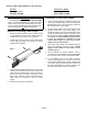
1. Remove endcap and lenses until you have access
to your lightbar’s power supply. Power supply is
located in the center section of your lightbar.
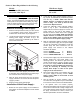
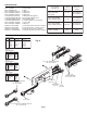
2. Locate the three harness plugs that connect to the
existing power supply. As shown in Fig.1, the
function of each plug is indicated by the outlet to
which it was connected.
3. Label each of the three plugs by their function. This
is important, as this will determine how these plugs
are connected to the new power supply.
4. With the plugs disconnected from the old power
supply, remove the two screws that hold the power
supply in position.
5. Remove power supply from lightbar.
Installation of New Power Supply...
1. Before the new power supply can be installed in
the lightbar, two harness adaptors must be added
as follows.
Rear
Modules
Front
Modules
Input
Control
Fig. 1
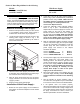
2. Locate the “ZF Input Harness Adaptor” shown in
Fig. 2 (P/N - 46-0741909-00). Install the 8 position
end onto Plug 1. NOTE - Make sure that the
adaptor harness is installed so that the wire
colors in Plug 1 are lined up with the wire
colors in the adaptor harness.
3. Locate the “2ZFO/ZF Output Harness Adaptor”
shown in Fig. 2 (P/N - 46-0741908-00). This
adaptor will be connected to plugs 2 & 3 of the new
power supply. As the ends of this adaptor are
identical, it doesn’t matter which end is plugged
into the power supply. NOTE - Make sure that the
adaptor harness is installed so that the wire
colors of the adaptor plugs are lined up with
the wire colors of the power supply’s plugs.
4. With the appropriate adaptor harnesses plugged
onto the new power supply, the new power supply
can now be connected to the lightbar. Locate the
harness plugs that were connected to the old
power supply and connect to the adaptor
harnesses as follows:
Connect POWER to PLUG 1
Connect REAR MODULES to PLUG 2
Connect FRONT MODULES to PLUG 3
5. The new power supply may now be mounted in the
lightbar. Position the new power supply in its
mounting location. This will be a tight fit and will
require a small amount of effort to properly mount
the new power supply. NOTE: If harness wraps
are present on the old lightbar plug harnesses,
it may be necessary to carefully cut and
remove these wraps in order for the power
supply to fit into the extrusion.
6. Secure the power supply to the lightbar using the
old power supply’s mounting screws. NOTE:
Apply Loctite™ #242 to the threads of each
mounting screw.
7. Test the lightbar for proper operation. After a
successful test, the lightbar may be reassembled
in the reverse order in which it was disassembled.
8. If the lightbar does not function properly,
disconnect the lightbar from its power source, wait
10 minutes to avoid the risk of a high voltage shock
and confirm that the proper plugs are connected. If
the plugs connections are correct, contact your
Whelen representative for further assistance.
WARNING!!!
The strobe light power supply is a HIGH VOLTAGE
device. You must wait at least 10 minutes after turning
off the power to the system before starting any diag-
nostic or trouble shooting procedures that may bring
you into contact with any
internal components.
Section 1; Retro-Fit guidelines for the following:
Models: With Power Supply:
9004SL, 9004WB, 9801, 9802,
9804, 9806, Mini Edge® ZF or 1ZF