
Manual


To cancel the timer function, press the button again ONCE.
E) Press button E to start the il motor at Speed 4. The speed is shown by the L4 GREEN LED coming ON. A single
pressure on the button when the led is on activates the timer function (motor on for 5'), shown by the flashing led.
To cancel the timer function, press the button again ONCE.
Grease filter/s: special attention must be given to the grease filters which must be periodically cleaned, whenever
the grease filter alarm trips. For instructions of the filter Alarm, refer to the Controls paragraph.
Depending on the version, the hood features different types of grease filters:
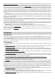
Modular metal filters (of the type shown in Fig. 17): To remove the filters: open the door pulling it forwards and
remove the filters pushing the catch upwards in correspondence to the handle. Wash the filters with a neutral
detergent. One time the grease filters are cleaned, to start the hours RESET again, press the button A for
2 seconds during the LEDS flashing.
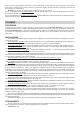
Panel type metal filter (of the type shown in Fig. 18N): this is a metal filter and it is positioned inside the metal grid. To
remove the filter: open the door pulling it forwards and push the 2 plastic catches upwards (Fig. 4). Remove the filter
retainers (Fig. 18Q) inside the metal grid and remove the panel type metal filter. For the filtering version, it is necessary,
to reach the filter, to remove the polyurethane filter too.
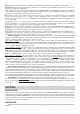
Panel type synthetic filter (of the type shown in Fig. 19P): this filter is made of white synthetic fibres and is located inside
the metal grid; it cannot be cleaned, but must be replaced from time to time according to use (at least every two months).
If the synthetic filter is not totally white, but has got coloured parts (stripes or spots), this means it is a saturation detector
filter, it should therefore be changed when the coloured parts can be seen from the outside or the apparatus. To remove
the synthetic filters: open the door pulling it forwards and push the 2 plastic catches upwards (Fig. 4). Remove the metal
filter clips (Fig. 19Q) and extract the filter. With the filtering version also the polyurethane filter needs to be removed. One
time the grease filters are cleaned, to start the hours RESET again, press the button A for 2 seconds during the LEDS
flashing.
Charcoal filters (or polyurethane): if the filtering version appliance is used, the charcoal filters (or polyurethane)
will have to be periodically replaced when the charcoal filter alarm trips. For instructions on the filter Alarm, refer to the
Controls paragraph. The filtering hood is supplied with different types of charcoal :
Round charcoal filters (Fig. 14T); to get to the round filters, take of f the anti-grease filters pushing the catch upwards
in correspondence to the handle (Fig.5); remove the charcoal filters from the motor block making them rotate
Polyurethane panel filters (Fig.15P): to get to the polyurethane filter, remove the grille making the 2 plastic catches get
upwards (Fig.4); inside the grille, take off the metal filter catches (Fig.15Q) so that the polyurethane filter can be removed.
Lighting: depending on the model bought, refer to Fig. 20 or Fig. 21.
Fig. 20: To remove the halogen lamps, unscrew the ring nut turning anticlockwise. Replace with lamps of the same type.
Fig. 21: To remove the
incandescent lamps, remove the light diffuser unscrewing the screw D. Replace with lamps of the
same type.
DEUTSCH
BESCHREIBUNG
Das Gerät kann im Umluft- oder im Abluftbetrieb verwendet werden. Beim Umluftbetrieb (Abb. 1) werden Luft und Dampf
von den Kohlefiltern (oder Polyurethanfiltern), während sie durch diese strömen, gereinigt und dann wieder in den Raum
zurückgeleitet. Im Abluftbetrieb (Abb. 2) werden Dampf und Küchengerüche durch eine Abluftleitung, die durch die Wand
oder die Decke geführt wird, direkt nach außen geleitet. In diesem Fall erübrigt sich die Verwendung der Kohle- oder
Polyurethanfilter.
INSTALLATION
Das Gitter oder die Fettfilter (je nach Modell) für eine leichtere Montage abnehmen und die frontseitige Klappe abbauen.
Demontage der Klappe: die Klappe öffnen, indem man sie nach vorne zieht; die 2 Schrauben D wie in Abb. 3 gezeigt
abdrehen. Die Lasche L niederhalten und die Klappe aus den Führungen ziehen.
Demontage des Gitters: die Klappe öffnen, indem man sie nach vorne zieht und die 2 Kunststoffriegel (Abb. 4) nach
oben schieben.
Demontage der Fettfilter: die Klappe öffnen, indem man sie nach vorne zieht; den Metallbügel beim Griff nach oben
schieben und den Filter (Abb. 5) herausziehen.
Es ist unerläßlich, daß vor der Montage: – sämtliche Vorbereitungen für den Stromanschluß getroffen werden.
– sofern das Gerät für Umluftbetrieb vorgesehen ist, die Öffnung zur Luftableitung gebohrt wird.
Bei der Absaugversion (nur für das auf Abb. 4 dargestellte Modell) kann die Luft zur Wand oder nach oben abgeleitet
werden; bei der Ableitung der Luft zur Wand den Flansch (F) auf der Rückseite und den Stopfen (T) über dem Gerät
positionieren (Abb. 6); bei der Ableitung der Luft nach oben umgekehrt vorgehen.
Vor der Montage des Gerätes ist es (nur für das auf der Abb. 5 dargestellte Modell) erforderlich:
- Abb. 7: den Flansch durch Verwendung der beiden mitgelieferten Schrauben auf das Gerät zu montieren.
- Abb. 8: die im Inneren des Gerätes befindliche Polystyrolplatte zu entfernen.
Montage : sicherstellen, daß die Haltebügel L am Gerät befestigt sind (Abb. 9); ggf. mit Feinstellschrauben (V) und
Unterlegscheiben (der Lieferung beigefügt) festspannen; desweiteren überprüfen, ob die 2 Feinstellschrauben (M)